Download
1 / 32
420 likes | 886 Views
Electric Bus Management System. Project Proposal William Chow, Amer Al- Mousa , Osama Mohammed . Electric Bus Management System. Project Overview Managerial Process Plans Technical Process Questions. Project Overview. Problem Outline Purpose, Scope, and Objectives Constraints

E N D
Electric Bus Management System Project Proposal William Chow, Amer Al-Mousa, Osama Mohammed
Electric Bus Management System • Project Overview • Managerial Process Plans • Technical Process • Questions
Project Overview • Problem Outline • Purpose, Scope, and Objectives • Constraints • Project Deliverables
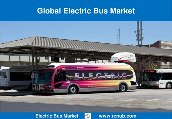
Problem Outline • Public transportation faces problems with pollutionand high fuel prices. • Currently no electric bus made by any North American manufacturer.
Purpose • The purpose of this project is to provide a flexible control system. • The system will provide an easy interface to add new electrical hardware. • Provide a GUI for the control system.
Scope • The scope of this project is only to provide a software control system. • The software control system will also be modular, so future software engineer students may add more features.
Objective • Provide a software foundation for later software engineering students to build upon. • Provide a working software control system for the electrical hardware supplied.
Constraints • The major Constraint is with how much hardware Electrodynamics is supplying. • No battery provided at this point.
Managerial Process Plans • Start-up Plan • Estimation Plan • Staffing Plan • Resource Acquisition Plan • Project Staff Training Plan • Work Plan • Deliverables (Work Activities) • Schedule Allocation • Control Plan • Requirement Control Plan • Schedule Control Plan • Quality Control Plan • Reporting Plan
Start-up Plan Estimation Plan: • Formal techniques and tools will be used estimate, track and evaluate the progress of the project (Rational Team Concert) RTC • Top-down approach is used to identify deliverables, sub-deliverables, up to the task level • Deliverables are grouped into a Work Breakdown Structure WBS • Tasks are implemented in a time-boxed iterations-sprint (2-4 weeks) • The progress of each task and its work package is tracked using automated project management tools
Start-up Plan - (Cont.) Staffing Plan: • Three of us should contribute equally into the project, and would beavailable for the wholeduration of the project Resource Acquisition Plan: • Any required resources, such as hardware, software, documentations, and any other type of resources, should be supplied by the client Project Staff Training Plan: • Educational sessions
Work Plan Deliverables (Work Activities): • The Documentations • The Software development Documentations • The Product Documentations • The GUI sub-systems • The Admin UI • The Dashboard UI • The Central Management System (CMS) • Helper Systems • Microcontrollers • Microcontroller to control motor • Microcontroller to simulate driver
Work Plan – (Cont.) Schedule Allocation:
Control Plan Requirement Control Plan • We do not expect many changes in the requirements • Changes are classified as a minor, or major changes • Risks to be highlighted at the very beginning Schedule Control Plan • Some of the deliverables have a fixed due dates and it should be respected • Tasks are sized and implemented in their assigned sprints, otherwise remaining work is carried over to next sprint as a technical debt • Planning tasks in short sprint is usually accurate
Control Plan – (Cont.) Quality Control Plan • The over all system undergoes different type of verifications tests • Every component has a Functional Verification Test Plan – FVT • Design reviews, Test Plan reviews, and Code reviews Reporting Plan • Tasks are placed in the sprint backlog, then assigned to team members • Team members report their progress of their individual backlogs • Automated tools are used for compute the sprint progress, and the over all progress
Technical Process • Electric Bus Management System (EBMS) • Technical System Overview • Tools and Programming Language • Process Model
The Electric Bus Management System (EBMS) is a system designed to control electrical devices or systems of an electric bus or vehicle EBMS
EBMS composed of several subsystems • 2 Different Software Systems • Central Management System (CMS) • GUI (Dashboard, Admin UI) • 2 Microcontrollers • Microcontroller to control Electric Motor • Microcontroller to interface with a Mechanical Device used to simulate a bus driver EBMS Components
2 Devices • Electric Motor (EBMS should be able to interact with any electrical device that can part of an electric bus) • Mechanical Device that issues commands simulating a bus driver Devices Interacting with EBMS
2 displays • Admin UI: simple console-like (Console Display) display to make it easy to add components to the system and print messages • Dashboard UI: Resembles the Dashboard of a car GUI
Central component of the EBMS • Updates Dashboard Display • Sends commands to electrical devices (through a microcontroller) • Receives commands from the driver simulator • Responds to commands issued through Admin UI CMS
They are programmable chips that are used to interact with electrical devices • Device Specific • CMS uses functions programmed into a microcontroller to communicate with an electrical device hooked up to the microcontroller. Microcontrollers
Black Arrow: Function Call Blue Arrow: Response Message
Tools • IDE used to help with programming lower layer (microcontrollers) • Programming Languages • Lower Layer: C • Higher Layer: C++, Java, or C Sharp • Hardware • 2 microcontroller (for the electric motor and for simulating a driver) • Server Machine – install CMS & GUI on it (or virtual server) • Electric motor • Network Protocol (to communicate with microcontrollers) Tools and Programming Languages
Electric Bus Management System • Project Overview • Managerial Process Plans • Technical Process • Questions