Download

1 / 34
340 likes | 468 Views
SCOUR IN LONG CONTRACTIONS. Rajkumar V. Raikar Doctoral Research Fellow Department of Civil Engineering Indian Institute of Technology Kharagpur INDIA. INTRODUCTION. Channel contraction - Reduction in width of waterway of river or channel

E N D
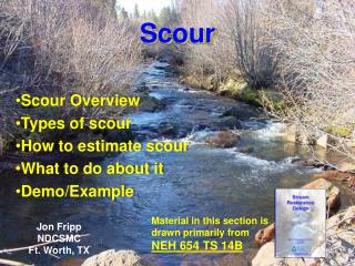
SCOUR IN LONG CONTRACTIONS Rajkumar V. Raikar Doctoral Research Fellow Department of Civil Engineering Indian Institute of Technology Kharagpur INDIA
INTRODUCTION Channel contraction - Reduction in width of waterway of river or channel Purpose - To reduce length of structure to minimize cost Examples - Bridges, barrages, weirs, cross-drainage works, cofferdams and end dump channel contractions used for the maintenance of the riverbanks
Classification of channel contractions - Long contractions for L/b1 > 1 (Komura, 1966) L/b1 > 2 (Webby, 1984) Present study - L/b1 1 L = length of contracted zone b1 = approaching channel width Effect - Increase in flow velocity Increase in bed shear stress
Classification of channel contractions - Long contractions for L/b1 > 1 (Komura, 1966) L/b1 > 2 (Webby, 1984) Present study - L/b1 1 L = length of contracted zone b1 = approaching channel width Effect - Increase in flow velocity Increase in bed shear stress Channel contraction scour
LITERATURE Straub (1934) - pioneer in long contraction - proposed one-dimensional theory Ashida (1963), Laursen (1963), Komura (1966), Gill (1981) and Webby (1984) - extended and modified Lim (1993) - empirical equation of equilibrium scour depth in long contractions
SCOPE • Earlier investigation on sand-beds • Estimation of scour depth in the gravel-beds within long contractions unexplored • Mathematical models developed for determination of scour depth inadequate
OBJECTIVES • Present investigation emphasizes on: • Experimental study of flow field within channel contractions • Parametric investigation on scour depth within long contractions through experimental study • Development of mathematical model for computation of scour depth within long contractions • Determination of empirical equation for maximum equilibrium scour depth within long contractions
EXPERIMENTATION Flume details: tilting flume (up to 1.7 %), 0.6 m wide, 0.7 m deep and 12 m long Contraction models: made of perspex sheets, Opening ratio, b2/b1= 0.7, 0.6, 0.5 and 0.4 Length of contracted zone: 1 m
Sediments used: uniform sediments, g < 1.4 median diameters (d50): Sand - 0.81 mm, 1.86 mm and 2.54 mm Gravel - 4.1 mm, 5.53 mm, 7.15 mm, 10.25 mm and 14.25 mm Approach flow velocity: 0.9 < U1/Uc < 0.98 U1 = average approaching flow velocity Uc = critical velocity for sediments
Study of flow field within channel contractions • Using acoustic Doppler velocimeter (ADV)
b1 x b2 (a) L 1 2 z h1 h2 x ds Bed sediment (b) 1 2 Schematic view of a long rectangular channel contraction b2 = contracted width of channel; h1 = approaching flow depth h2 = flow depth in contracted zone; ds = equilibrium scour depth
increases with increase in up to section of maximum scour depth and then gradually decreases. In the downstream, it diminishes gradually with enlargement. Vertical distribution of normalized streamwise velocity component (= u/U1) along the centerline for the channel opening ratios: (a) 0.7, (b) 0.6, (c) 0.5, and (d) 0.4
is negative, indicating downward direction, that is responsible for contraction scour, in addition to bed shear stress. Vertical distribution of normalized vertical velocity component (= w/U1) along the centerline for the channel opening ratios: (a) 0.7, (b) 0.6, (c) 0.5, and (d) 0.4
1 Normalized velocity vectors along the centerline for the channel opening ratios: (a) 0.7, (b) 0.6, (c) 0.5, and (d) 0.4
Parametric study 1 2 = ds/b1 = d50/b1 Fo = densimetric Froude number,U1/(gd50)0.5 = h1/b1 = channel opening ratio, b2/b1 g = non-uniformity coefficient of bed sediment
Variation of with Variation of with Fo
Variation of with Variation of with
Development of mathematical model • Clear-water scour – energy and continuity equations • Live-bed scour – energy, continuity and sediment continuity equations Clear-water scour model Energy and continuity equations applied between sections 1 and 2 for flow situation at equilibrium condition 4 5 U1 = approaching flow velocity; U2 = flow velocity in contracted zone; hf = head loss between sections 1 and 2 [negligible for contractions with gradual transition (Graf 2003)]
Determination of scour depth with sidewall correction For the equilibrium scour depth ds to reach in a long contraction, the flow velocity U2 critical velocity Uc for sediments The flow velocity : 6 u*c = critical shear velocity for sediments obtained from the Shields diagram fb = friction factor associated with the bed evaluated by the Colebrook-White equation 7
ks = equivalent roughness height (= 2d50) Ab = flow area associated with the bed Pb = wetted perimeter associated with the bed (= b2) Rb = flow Reynolds number associated with the bed [= 4Ab/(Pb)] Vanoni’s (1975) method of sidewall correction applied: 8 A = total flow area (= h2b2) Pw = wetted perimeter associated with the wall (= 2h2) For clear-water scour, the continuity equation, Eq. (5): 9
Eqs. (6) - (9) solved numerically to obtain , h2, Rb and fb Equilibrium scour depth ds obtained from Eq. (4): 10 The comparison of nondimensional equilibrium scour depths (= ds/h1) computed from Eq. (10) with experimental data is shown:
Comparison between experimental data and computed values of equilibrium scour depths using clear-water scour model with sidewall correction
Determination of scour depth without side wall correction Following semi-logarithmic average velocity equation used along with Eq. (9) to find and h2 11 Equilibrium scour depth ds obtained by Eq. (10) Comparison of nondimensional equilibrium scour depths (= ds/h1), for this case, with experimental data shown:
Comparison between experimental data and computed values of equilibrium scour depths using clear-water scour model without sidewall correction
Live-bed scour model: • Equilibrium scour depth ds attained • sediment supplied by the approaching flow into the contracted zone equaling sediment transported out of the contracted zone • At equilibrium • - sediment continuity equation between sections 1 and 2: 12 = bed-load transport of sediments, estimated by Engelund and Fredsøe (1976) equation 13 u* = shear velocity
At section 1, shear velocity u*1: 14 Substituting u*2 in Eq. (5): 15 Eqs. (12), (14) and (15) solved numerically to obtain U2 and h2 Equilibrium scour depth ds determined from Eq. (4) as 16 The comparison of nondimensional equilibrium scour depths computed using model with live-bed scour data shown:
Comparison between the equilibrium scour depths computed using live-bed scour model and the experimental data
Empirical equation for maximum equilibrium scour depth: From Eq. (1) using dimensional analysis, 17 = ds/h1; F1e = excess flow Froude number, U1e /(gh1)0.5; U1e = excess velocity of flow, U1 – = d50/h1 From experimental data, with regression analysis 18
Comparison between experimental data and computed values of equilibrium scour depths using empirical equation
CONCLUSIONS • The velocity vectors reveal that velocity increases towards the zone of maximum scour depth and then decreases • Scour depth increases with increase in sediment size for gravels. Curves of scour depth versus sediment size have considerable sag at transition of sand and gravel • Scour depth gradually reduces with increase in densimetric Froude number for larger opening ratios. However, for small opening ratios, trend is opposite • Scour depth increases with increase in approaching flow depth at lower flow depths, but it becomes unaffected by approaching flow depth at higher flow depths
Scour depth increases with decrease in contracted width of channel • Nonuniform sediments reduce scour depth to a great extent due to formation of armor-layer within scour hole • Scour depths computed using the models are in excellent agreement with the experimental data • Characteristic parameters affecting maximum equilibrium nondimensional scour depth, have been excess approaching flow Froude number, sediment size - approaching flow depth ratio, and channel opening ratio