Download
1 / 23
230 likes | 351 Views
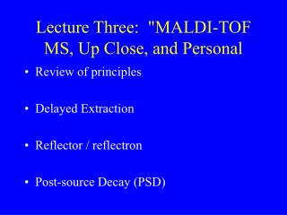
A small accelerator mass spectrometer with a gas chromatographic inlet/interface. Barbara Hughey, Bob Klinkowstein, Ruth Shefer Newton Scientific, Inc. Paul Skipper, John Mehl, Pete Wishnok, Steve Tannenbaum MIT Division of Bioengineering and Environmental Health. 10 μg carbon.

E N D
A small accelerator mass spectrometerwith a gas chromatographic inlet/interface. Barbara Hughey, Bob Klinkowstein, Ruth Shefer Newton Scientific, Inc. Paul Skipper, John Mehl, Pete Wishnok, Steve Tannenbaum MIT Division of Bioengineering and Environmental Health
10 μg carbon 6 X 10⁵ atoms 14C 1 attomole 14C (t= 5730 years) ß- AMS scintillation counter 1000 counts in 14 years 1000 counts in 2 minutes Comparing AMS to scintillation counting AMS counts the number of atoms in tbe sample, while scintillation counters measure the infrequent radioactive decay events in the sample.
Applications of accelerator mass spectrometry AMS can be used for any experiment that is currently done by scintillation counting, but is faster and requires much less radioactivity. Drug development Toxicology (low-level, I.e., ambient dose-response) Human metabolism and distribution Trace analysis by post-labeling Geochemistry - radiocarbon dating • Experiments can be done on humans • Minimum precautions needed during synthesis of reagents • No regulations involved in disposal
Why is accelerator mass spectrometry not widely used? 1. Current instruments are generally large and expensive, and often require dedicated facilites and an operational staff. 2. Sample preparation is time-consuming and skill-intensive.
gas chromatograph oxidizer gas-fed ion-source detector • GC: • Oxidizer: • AMS system: sends pure compounds into the oxidizing interface. converts these compounds into a chemical form amenable to gas-fed ion-source. measures the amount of carbon-14 in the sample. Schematic of a GC-AMS system complex organic molecules C- and other negative ions CO2 14C2+ AMS accelerator system with low- and high- energy analyzers AMS accelerator and detection system sample separation and injection interface
Q. Why can such low levels of 14C be quantitated? A. Because the natural abundance is also low. With a low backround, anything much above background can be measured; there is very little interference. This is especially useful in experiments with samples that have been enriched with carbon-14 since very little enrichment is needed in order to have detectable signal.
Q. But why does it take a complex, expensive system toquantitate the 14C? A. Because - even though there is very little 14C relative to 12C, there is a very high abundance of other substances with very similar atomic or molecular weights: 12CH213CH N A combination of negative-ion formation followed by high-energy collisions with gas or thin foils eliminates interference from these substances.
Schematic of the NSI/MIT GC-AMS Cesium Sputter Negative Ion Source People standing around Oxidizer GC Detector High Energy Analyzing Magnet Low Energy Analyzing Magnet Low Energy Accelerating Tube Electrostatic analyzer Carbon Stripping Foil Carousel High Energy Accelerating Tube
Oxidation and ionization The CO2 (and ambient nitrogen) is converted to negative ions by bombardment with high-energy Cs ions. 16O- Cs sputter source oxidizer 12C- sample CO2 13C- CuO 750oC 14C- 13CH- 12CH2- N- As each compound elutes from the GC, it’s converted to CO2 by an on-line oxidizer. N- is unstable, and decomposes.
Oxidation and ionization The CO2 (and ambient nitrogen) is converted to negative ions by bombardment with high-energy Cs ions. 16O- Cs sputter source oxidizer 12C- sample CO2 13C- CuO 750oC 14C- 13CH- 12CH2- As each compound elutes from the GC, it’s converted to CO2 by an on-line oxidizer. N- is unstable, and decomposes.
Isolation of the 14 Da isobars 16O- The negative ions of higher and lower weight are easily removed with a low-energy magnetic sector, sending only the 14-dalton substances into the accelerator. 12C- 13C- magnet 1 14C- 13CH- 12CH2- 14C- 13CH- 12CH2- 16O- 12C- 13C-
Conversion to atomic ions accelerator/stripper 14C- 13CH- 12CH2- 14Cn+ 13Cn+ 12 Cn+ The isobars are then accelerated to(a maximum of) 1 MEV and collided with a thin foil. • Polyatomic structures are destroyed. • Some electrons are stripped, leaving positive ions.
Detection of 14C electrostatic sector magnetic sector 14Cn+ 13Cn+ 12 Cn+ 14Cn+ These ions - now with different m/z values - are brought down to ground potential and sent through an electrostatic analyzer and a high-energy magnetic sector to send (finally) only carbon-14 into the detector.
Our original test mixture. These were chosen because they were handy, because they were aromatic and thus potentially difficult to oxidize, and because they contained a variety of heteroatoms. 2 acetanilide C8H9NO 3 diethylphthalate C12H14O4 4 4-chlorodiphenyl ether C12H9ClO 1 methyl phenyl sulfide C7H8S 5 benzophenone C13H10O 6 9-fluorenone C13H8O 7 phenanthrene C14H10
7 5 6 4 3 1 2 m/z = 44 4.00 5.00 6.00 7.00 8.00 Retention time Online oxidation of organics to CO2 In this experiment, the previous mixture was separated by capillary GC and then sent through the CuO oxidizer into a small mass spectrometer that was set to detect only m/z 44. The number of carbons in the mixture was the same for each component. The oxidizer cleanly and efficiently converted each component to CO2.
350 CO2 CO2 CO2 CH4 CO2 CO2 CH4 CH4 CH4 CH4 300 12C- current (μA) 250 each injection = 100 pmoles 200 0 1 2 3 4 5 6 Time (min) Conversion of CO2 to C- In this experiment, alternate injections of CO2 and methane were flow-injected through the oxidizer and into the Cs sputter ion source. The methane was quantitatively converted into CO2, giving essentially identical C- signals for each substance.
New test mixture, old GC column. A new version of the test mixture was prepared without methylphenyl sulfide. (It decomposed, and it smelled bad.) This experiment is identical with the earlier one using the small mass spectrometer as a CO2 detector. The oxidizer is working well, but the chromatography has deteriorated - peaks 3 and 4 are no longer resolved. 3 4 7 5 6 2 m/z = 44 3.00 4.00 5.00 6.00 Retention time
12C- current (nA) 110 3+4 105 100 5 7 95 6 90 2 85 80 75 70 5.0 5.5 6.0 6.5 7.0 7.5 8.0 8.5 9.0 Time (min) Online conversion of CO2 from organic molecules into C- The previous test mixture was separated by capillary GC, sent through the CuO oxidizer and through the Cs sputter ion-source. The negative ion current from carbon-12 was detected by a Faraday cup after the low-energy magnet. The chromatographic peak shapes are acceptable.
Carbon-14 window Mass-13 Faraday cup Detection of a 14CO2 pulse. Enriched CO2 was flow injected into the Cs sputter ion source, carbon-13 was detected by a Faraday cup after the low-energy magnet and carbon-14 was detected as positive ions at the end of the entire AMS system with essentially no memory effect. 1400 0.6 1200 0.5 1000 Counts in 14C window Mass-13 negative ion current (μA) 800 0.4 600 0.3 400 200 0.2 0 0 10 20 30 40 50 Time (sec)
Summary • We’ve shown so far that: • The oxidizing interface works; • The chromagraphy is pretty good; • The ion-source works; • The accelerator/stripper works; • The device transmits 14C. • I.e., that all the parts are in place. • What we’ll do next: • Optimize 14C ion transmission; • Characterize the complete GC-AMS system; • Finish development of LC-AMS interface; • Run some real samples.
Thanks Tom Doucette, Dennis Clarke, and Andrew Dart are NSI engineers who’ve helped with design and construction. Naomi Fried and Kaisheng Jiao were postdoctoral fellows who helped with the early exploratory experiments. Financial support has been primarily through small business grants from The National Institutes of Health and the National Science Foundation