Download
1 / 43
440 likes | 618 Views
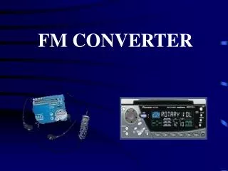
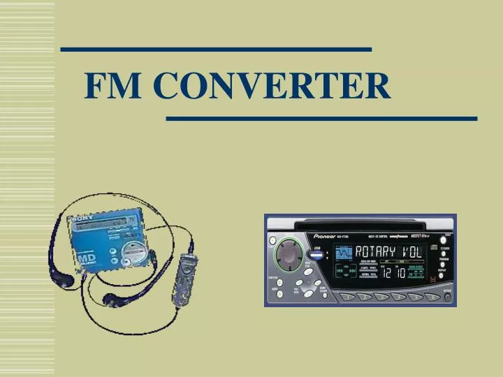
FM CONVERTER. Team Members. Dan Harkins. Beau Blackwell. Dr. Georgios Lazarou Advisor. Shawn Welch. George Henry Team Leader. Daniel Lack. Team Responsibilities. Implementation. Block Diagram. LCD. Pre-Emphasis. Modulator. Amplifier. Modulator. LCD. Pre-Emphasis. Modulator.

E N D
Team Members Dan Harkins Beau Blackwell Dr. Georgios Lazarou Advisor Shawn Welch George Henry Team Leader DanielLack
Block Diagram LCD Pre-Emphasis Modulator Amplifier
Modulator LCD Pre-Emphasis Modulator Amplifier
Modulator • Design Requirements: • Tunable • FM Radio Quality
Modulator • Design Requirements: • Tunable • FM Radio Quality • Alternate topologies
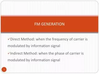
Alternate Modulator Topologies Direct FM Modulation of a Crystal Oscillator
Modulator • Design Requirements: • Tunable • Radio SNR • Alternate topologies • Carrier Signal
Modulator • Design Requirements: • Tunable • Radio SNR • Alternate topologies • Carrier Signal • Inductor choice
Modulator • Capacitor choice • Frequency range (88.1-88.5)
FCC Separation Standards Courtesy of: http://www.fcc.gov/mmb/asd/spacing/73207.html
Pre-Emphasis LCD Pre-Emphasis Modulator Amplifier
Pre-Emphasis • Requirements: • Process standard audio input for modulator • Voltage regulation • Filter
Simulation of Pre-Emphasis Input 1 Output Input 2
Pre-Emphasis Hardware Results P-Spice Simulation Hardware Results
Amplifier LCD Pre-Emphasis Modulator Amplifier
Amplifier • Requirements • FCC regulations • Signal amplification • Preparation for transmission
Converter Schematic Pre-Emphasis
Converter Schematic Modulator
Converter Schematic Amplifier
Display Network Schematic • Driven by PIC16F84 • Displays operating frequency to user • Prompts user to set radio • Largest power consumption Digital Interface
PCB Layout Fabricated by Express PCB
Input vs. Output CH A: Audio Input CH B: Audio Output Tone FM Signal
Input vs. Output Input Output 5kHz 10kHz 15kHz
Power and Battery Life • Uses 4 AA batteries • Current: • With LCD backlit: 118mA • Normal operation: 28mA • Battery life: • Worst case (LCD on constantly): ~ 89 hours (3.7 days) • Best case (LCD on ~0%): ~ 407 hours (17 days) • Normal use (LCD on 2%): ~ 382 hours (16 days) Courtesy of: http://data.energizer.com
3.5 inches Packaged Product Depth = 1.5 inches Volume = 36.75 in3 7 inches
Developments • Stereo development • BA1404
Acknowledgments Thank you: • Dr. Lazarou • Dr. Picone