Download
1 / 14
140 likes | 244 Views
The muon Drift Tubes pulsing scheme. Roberto Cirio CERN, march 8 2001 Calibration Working Group meeting. Why pulsing DTs ?. Simulate tracks on a single chamber Test setup during installation Test Front End response Special runs Monitor readout and trigger synchronization Abort gap.

E N D
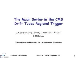
The muon Drift Tubes pulsing scheme Roberto Cirio CERN, march 8 2001 Calibration Working Group meeting
Why pulsing DTs ? • Simulate tracks on a single chamber • Test setup during installation • Test Front End response • Special runs • Monitor readout and trigger synchronization • Abort gap R.Cirio - DT pulsing scheme
The muon drift tubes • Each of the 60 sectors (4 chambers): • sends data to one channel of the DDU • Each chamber (<1024 channel): • 8 layers of Rf wires connected to FE_boards and RO_boards • is controlled by one Control Board • preamplifier input can receive a test pulse R.Cirio - DT pulsing scheme
FE_board FE_board FE_board FE_board FE_board FE_board CONTROL board RO_board RO_board RO_board Test Pulse Left/Right Test Pulse 1 Test Pulse 2 On-chamber control network TTC signals From TTC On-chamber minicrate Chamber R.Cirio - DT pulsing scheme
Detector Control System Slow Control Master CONTROL Board RS485-optical links Loading pattern sequences on Control Boards • Patterns are loaded on the Control Board and Readout board registers via slow control • Feedback can be given to Run Control via the Detector Control System • Patterns can be loaded without stopping data taking R.Cirio - DT pulsing scheme
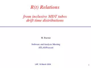
1 15 8 1 2 7 8 7 2 16 15 16 9 9 13 13 61 61 63 63 10 10 14 14 62 62 64 64 Superlayer 1 EN_1 EN_2 EN_3 EN_4 EN_16 Superlayer 2 11 6 12 5 3 4 5 6 12 3 4 11 Pulsing a DT chamber: cells 1,2,3,4 R.Cirio - DT pulsing scheme
Pulsing a DT chamber: cells 1,2,3,4 • Activate: • Enable_1 • Yellow cells and blue cells (Test Pulse Left/Right) • Delay_1-2 (Test Pulse 1) and delay_3-4 (Test Pulse 2) are set (<400 ns) R.Cirio - DT pulsing scheme
1 15 8 1 2 7 8 7 2 16 15 16 9 9 13 13 61 61 63 63 10 10 14 14 62 62 64 64 Superlayer 1 EN_1 EN_2 EN_3 EN_4 EN_16 Superlayer 2 11 6 12 5 3 4 5 6 12 3 4 11 Pulsing a DT chamber:cells 3,4,5,6 R.Cirio - DT pulsing scheme
Pulsing a DT chamber:cells 3,4,5,6 • Activate: • Enable_1 and Enable_2 • Blue cells (Test Pulse Left/Right) • Delay_5-6 (Test Pulse 1) and delay_3-4 (Test Pulse 2) are set (<400 ns) R.Cirio - DT pulsing scheme
1 15 8 1 2 7 8 7 2 16 15 16 9 9 13 13 61 61 63 63 10 10 14 14 62 62 64 64 Superlayer 1 EN_1 EN_2 EN_3 EN_4 EN_16 Superlayer 2 11 6 12 5 3 4 5 6 12 3 4 11 Pulsing a DT chamber: cells 5,6,7,8 R.Cirio - DT pulsing scheme
Pulsing a DT chamber: cells 5,6,7,8 • Activate: • Enable_2 • Blue cells and yellow cells (Test Pulse Left/Right) • Delay_5-6 (Test Pulse 1) and delay_7-8 (Test Pulse 2) are set (<400 ns) R.Cirio - DT pulsing scheme
Sequence of control signals • RO_boards and Control_Board get the sequence of patterns • TTC sends the Test Pulse Preset • Control Board generates • Test Pulse Advance: load next pattern • Test Pulse Inject: pulse chamber • Test Pulse Reset: go to readout mode • TTC sends LV1A R.Cirio - DT pulsing scheme
CB: TP 1 CB: TP 2 CB: TP Reset TTC: LV1A Control signals: timing diagram TTC Test Pulse (TP) Preset Control Board (CB):TP Advance <400 ns Window for TDC readout equal to trigger latency R.Cirio - DT pulsing scheme
Data volume • Depending on chamber size, 4 to 8 tracks are generated • In each sector, 1 out of 4 chambers will be pulsed • Maximum data volume is equivalent to 2 tracks per sector R.Cirio - DT pulsing scheme