Download
1 / 40
400 likes | 502 Views
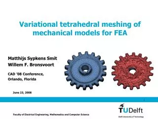
Simplification and Improvement of Tetrahedral Models for Simulation. Barbara Cutler, MIT Julie Dorsey, Yale Leonard McMillan, UNC - Chapel Hill. Motivation. Physical simulations are now in widespread use in computer graphics Interactive deformation & fracture simulations

E N D
Simplification and Improvement of Tetrahedral Models for Simulation Barbara Cutler, MIT Julie Dorsey, Yale Leonard McMillan, UNC - Chapel Hill
Motivation • Physical simulations are now in widespread use in computer graphics • Interactive deformation & fracture simulations • However, preparing appropriate models is challenging
Motivation 300 bone tetras 850 skin tetras (head only) 1,200 bone tetras 800 skin tetras [Cutler et al. 02] & [Müller et al. 02]
Contributions • Simplification and shape improvement to meet interactive simulation requirements • Element quality metric • Models from high-resolution scanned meshes with interior boundaries • Robust & efficient implementation
Overview • Previous Meshing Research • Mesh Generation • Mesh Simplification • Mesh Improvement • Mesh Refinement • Goals and Requirements • Algorithm • Results • Conclusions & Future Work
Mesh Generation Given some boundary, fill the interior with elements • Advancing Front / Advancing Layers [Lohner 88, Pirzadeh 96] • Delaunay Triangulation [Baker 89, Shewchuk 97, Cavalcanti & Mello 99, Persson & Strang 04] • Structured/Octree Tetrahedralization [Yerry & Shepard 84, Nielson & Sung 97]
Mesh Simplification Reduce the overall number of elements • Progressive Mesh - edge collapses only • 2D [Hoppe 96] • 3D [Staadt 98, Cignoni et al. 00, Chiang & Lu 03, Natarajan & Edelsbrunner 04] • Complex transformations – more difficult to implement, allows topology change • 2D [Shroeder et al. 92, Turk 92] • 3D [Trotts et al. 98, Chopra & Meyer 02]
Mesh Improvement Improve the quality/shape of elements in the mesh • Local transformations to improve shape[Frey & Field 91, Hoppe et al. 93, Joe 95] • Sliver removal from Delaunay Triangulations[Cheng et al. 99, Edelsbrunner & Guoy 02] • Combination of transformations more effective than a single type[Freitag & Ollivier-Gooch 97]
Mesh Refinement Increase the local resolution of the mesh (while maintaining element quality) • Regular Subdivision [Bank et al. 83, Bey 95, Edelsbrunner & Grayson 00] • Edge Bisection [Alder 83, Rivara & Levin 92, Liu & Joe 95, Maubach 95, Arnold et al. 00]
Overview • Previous Meshing Research • Goals and Requirements • Element Quality Metric • Algorithm • Results • Conclusions & Future Work
Goals and Requirements • Reduce the overall number of elements • Maintain the material boundaries • Improve the shape of each element • Reasonable distribution of elements • Robustness • Scalability
Why is Element Shape Important? • Very small dihedral angles →the stiffness matrix is constrained [Babuska & Aziz 76] • Very large dihedral angles →errors in FEM increase [Krizek 92] • All elements must meet minimum shape requirements
Element Quality Metric Geometric mean of 3 components: • Shape • minimum solid angle (equilateral ≈ 0.55 steradians) • Volume • ideal volume = • Edge Length • ideal edge length = 3√ ideal volume total volumetarget tetra count
Overview • Previous Meshing Research • Goals and Requirements • Algorithm • Local mesh transformations • Block iteration • Results • Conclusions & Future Work
Local Mesh Transformations • Tetrahedral Swaps • Edge Collapse • Vertex Smoothing • Vertex Addition
Local Mesh Transformations • Tetrahedral Swaps • Choose the configuration with the best local element shape • Edge Collapse • Vertex Smoothing • Vertex Addition
Local Mesh Transformations • Tetrahedral Swaps • Edge Collapse • Delete a vertex & the elements around the edge • Vertex Smoothing • Vertex Addition Before After
Prioritizing Edge Collapses Spanning: never collapse Boundary: check error • Preserve topology • Thin layers should not pinch together • Collapse weight • Edge length + boundary error • No negative volumes • Local element quality does not significantly worsen Boundary-Touching:one-way collapse Interior: ok to collapse
Local Mesh Transformations • Tetrahedral Swaps • Edge Collapse • Vertex Smoothing • Move a vertex to the centroid of its neighbors • Convex or concave, but avoid negative-volume elements • Vertex Addition Before After
Local Mesh Transformations • Tetrahedral Swaps • Edge Collapse • Vertex Smoothing • Vertex Addition • At the center of a tetra, face, or edge • Useful when mesh is simplified, but needs further element shape improvement
Ensuring Consistency • Prevent mesh degeneracies • Examine the neighbors sharing each face, edge and vertex • (see paper for list) • Implementation must be tolerant of negative- and zero-volume elements • May be present in input models or at intermediate stages of deformation
Block Iteration Algorithm while (tetra count > target tetra count) T = a subsetof all elements randomly reorder T foreach tT, try: • tetrahedral swaps • edge collapse • move vertex • add vertex Look for an action that improves or removes this element
Block Iteration Algorithm E is the allowable boundary error E = ideal edge length while (tetra count > target tetra count) T = a subsetof all elements randomly reorder T foreach tT, try: • tetrahedral swaps • edge collapse • move vertex • add vertex E *= As ∆E → 0, the Block Iteration Algorithm is equivalent to a Progressive Mesh √ tetra count target tetra count 3
Block Iteration Algorithm E = ideal edge length percent = 10% while (tetra count > target tetra count) T = the poorest percent of all elements randomly reorder T foreach tT, try: • tetrahedral swaps • edge collapse • move vertex • add vertex E *= percent += 10% The Block Iteration Algorithm is a partial orderNot all of the edge weights must be recomputed before the next transformation √ tetra count target tetra count 3
Computing Edge Collapse Weight • Expensive to determine legality of collapse, especially in 3D • On average 100 edge weights are invalidated when an edge is collapsed • Progressive Mesh maintains a priority queue of all collapse weights (total order) Before After
Edge Collapse Weight Recomputation Edge collapse weight re-computation dominates the running time (~80%)
Overview • Previous Meshing Research • Goals and Requirements • Algorithm • Results • Meshes, Performance, Quality • Comparison to Previous Work • Conclusions & Future Work
Results: Hand original (100K faces) 10K tetras (7K faces) 100K tetras (57K faces) 30K tetras (19K faces)
Results: Dragon original (100K faces) 100K tetras (48K faces) 5K tetras (3K faces)
Performance Extreme simplification is faster because E, the allowable error, is larger (optimizing over fewer elements)
Performance Edge collapse weight re-computation dominates the running time (~80%)
Visualization of Element Quality good angle, but small-volume 1,050K tetras(133K faces) zero-angle &zero-volume near-equilateral& ideal-volume
Visualization of Element Quality Octree or Adaptive Distance Field (ADF) 461K tetras(108K faces)
Visualization of Element Quality After Simplification& Mesh Improvement 10K tetras(3K faces)
Variety of Transformations All Transformations Edge Collapse Only More likely to contain poor quality elements or require large boundary error, E
Overview • Previous Meshing Research • Goals and Requirements • Algorithm • Results • Conclusions & Future Work
Conclusions • Element quality metric • Robust & efficient implementation • Ensures removal of poorest quality elements to meet FEM requirements • Encourages iterative modeling
Future Work • Switch to a total-order mesh optimization (e.g. Progressive Mesh) at end to improve performance • Order of transformations attempted • Multiple transformation look-ahead • Topological simplification • Online local re-meshing & refinement
Thank You • Matthias Müller, Rob Jagnow, Justin Legakis, Derek Bruening, Frédo Durand • MIT Computer Graphics Group