Download
1 / 13
130 likes | 142 Views
Ferrite measurements of Mu2e AC dipole. Summer Student Meeting August 25, 2010 Student: Evgeny Bulushev , NSU Supervisor: George Velev, TDMagnet Systems Department. Mu2e Experiment. Typical muon decay: μ → e ν μ ν e

E N D
Ferrite measurements of Mu2e AC dipole Summer Student Meeting August 25, 2010 Student: Evgeny Bulushev , NSU Supervisor: George Velev, TD\Magnet Systems Department
Mu2e Experiment • Typical muon decay: • μ → e νμνe • μ-e conversions without conservation of lepton flavor are predicted by SM with signal Rμe<10-54 • Most supersymmetric models predict rates >> SM, with signal Rμe ~ 10-15 • Mu2e experiment searches for a μ-e conversion with sensitivity Rμe ~ 6×10-17
Experiment conditions Requirements: • To achieve 6×10-17 sensitivity for every proton in the bunch there has to be fewer than 10-9 out-of-time protons Goal: • To perform beam background cleaning up Decision: • Alternating magnet field can be used to clean up beam background 100 ns proton bunches separated with 1.7 μs gap (~600 kHz)
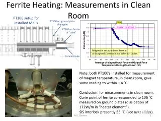
Clean up principles • Problem: • Overheating of ferrite magnets. • B-H curve (Hysteresis) loss • Eddy current loss collimator out of time beam MnZn NiZn in time beam ν = 300KHz B =180 G ν = 5.1MHz B = 9G
Tasks Ferrite plate 1) Experimental • Set up measurements of magnetic properties and some thermo parameters of MnZn and NiZn ferrites • Analyze data purposely to optimize ferrite plate geometry 2) Theoretical • Simulate magnetic flux distribution and energy loss in ferrite plate using ANSYS
Experiments Geometry Conditions • Ferrite type: MnZn, NiZn • Generator amplitude: 0.5V, 0.35V, 0.25V, 0.1V • Generator Frequency: 25kHz, 100kHz, 300kHz, 5.1MHz «1 plate» geometry ferrite 10 mm «2 plate» geometry isolator ferrite 10 mm ferrite
Simulation Model Results
Conclusion 1) Magnetic and thermo properties of MnZn and NiZn ferrites were measured. 2) Experiments have shown that 2 plate geometry leads to twice lower heating in the MnZn ferrite plates, as expected. 3) Ferrite plate model was created; field distribution and energy loss were simulated in ANSYS – first results are coming. Plans: - Simulate thermo distribution in ferrite plate - Compare experimental and simulation results - Provide data analyses of experimental results