Download
1 / 25
260 likes | 538 Views
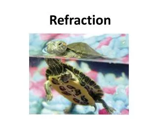
Electromagnetic waves: Reflection, Refraction and Interference. Friday October 25, 2002. Optical cooling. Photons. v. k. m. Because of its motion, the atoms “see” an incoming photon with a frequency Doppler-shifted upward by,.

E N D
Electromagnetic waves: Reflection, Refraction and Interference Friday October 25, 2002
Optical cooling Photons v k m Because of its motion, the atoms “see” an incoming photon with a frequency Doppler-shifted upward by, Laser frequency (fL) chosen to be just below the resonance frequency of the atom (fo) fo = fL(1+v/c)
Optical Cooling Photons of the right frequency will be absorbed by the atom, whose speed is reduced because of the transfer of the momentum of the photon, Emission occurs when the atom falls back to its ground state. However, the emission is randomly directed An atom moving in the opposite direction, away from the light source, sees photons with a frequency, fL(1-v/c),far enough from fo that there can be little or no absorption, and therefore no momentum gain. Radiation pressure force : As v decreases, there must be a corresponding change in the laser frequency….. One must have three mutually perpendicular laser beams in order to reduce the speed of the atoms in all directions.
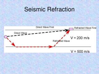
Reflection and Transmission at an interface Normal Incidence – Two media characterized by v1, v2 incident transmitted reflected 1 2
Reflection and Transmission at an interface • Require continuity of amplitude at interface: f1 + g1 = f2 • Require continuity of slope at interface: f1’+ g1’= f2’ • Recall u = x – vt
Reflection and Transmission at an interface Continuity of slope requires, or,
Reflection and Transmission at an interface • Integrating from t = - to t = t • Assuming f1(t = - ) = 0 • Then,
Amplitude transmission co-efficient () Medium 1 to 2 Medium 2 to 1
Amplitude reflection co-efficient () At a dielectric interface
Phase changes on reflection from a dielectric interface n2 > n1 n2<n1 Less dense to more dense e.g. air to glass More dense to less dense e.g. glass to air phase change on reflection No phase change on reflection
Phase changes on transmission through a dielectric interface Thus there is no phase change on transmission
Amplitude Transmission & Reflection For normal incidence Amplitude reflection Amplitude transmission Suppose these are plane waves
Intensity reflection Amplitude reflection co-efficient and intensity reflection
Intensity transmission Intensity transmission and in general R + T = 1 (conservation of energy)
Two-source interference What is the nature of the superposition of radiation from two coherent sources. The classic example of this phenomenon is Young’s Double Slit Experiment Plane wave () P S1 y x a S2 L
Young’s Double slit experiment Assumptions • Monochromatic, plane wave • Incident on slits (or pin hole), S1, S2 • separated by distance a (centre to centre) • Observed on screen L >> a (L- meters, a – mm) • Two sources (S1 and S2) are coherent and in phase (since same wave front produces both as all times) • Assume slits are very narrow (width b ~ ) • so radiation from each slit alone produces uniform illumination across the screen
Young’s double slit experiment • slits at x = 0 • The fields at S1 and S2 are Assume that the slits might have different width and therefore Eo1 Eo2
Young’s double slit experiment What are the corresponding E-fields at P? Since L >> a ( small) we can put r = |r1| = |r2| We can also put |k1| = |k2| = 2/ (monochromatic source)
Young’s Double slit experiment The total amplitude at P Intensity at P
Interference Effects • Are represented by the last two terms • If the fields are perpendicular • then, • and, In the absence of interference, the total intensity is a simple sum
Interference effects • Interference requires at least parallel components of E1P and E2P • We will assume the two sources are polarized parallel to one another (i.e.
Interference terms where,
Intensity – Young’s double slit diffraction Phase difference of beams occurs because of a path difference!
Young’s Double slit diffraction • I1P = intensity of source 1 (S1) alone • I2P = intensity of source 2 (S2) alone • Thus IP can be greater or less than I1+I2 depending on the values of 2 - 1 • In Young’s experiment r1 ~|| r2 ~|| k • Hence • Thus r2 – r1 = a sin r1 r2 a r2-r1