Download
1 / 47
470 likes | 680 Views
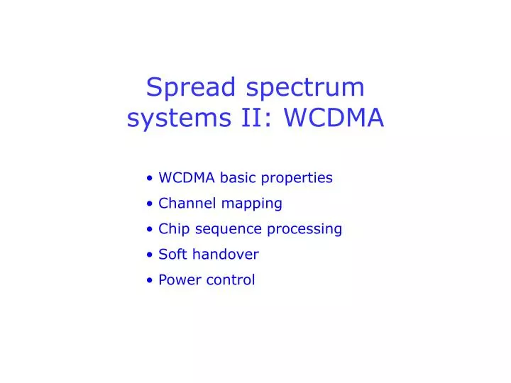
Spread spectrum systems II: WCDMA. WCDMA basic properties Channel mapping Chip sequence processing Soft handover Power control. 1. WCDMA basic properties. Issues / important concepts: Two duplex alternatives: UTRA FDD vs. UTRA TDD Spectrum allocation (UTRA FDD)

E N D
Spread spectrum systems II: WCDMA • WCDMA basic properties • Channel mapping • Chip sequence processing • Soft handover • Power control
1. WCDMA basic properties • Issues / important concepts: • Two duplex alternatives: UTRA FDD vs. UTRA TDD • Spectrum allocation (UTRA FDD) • Spreading in WCDMA • DPDCH/DPCCH/DPCH channel bit rates
Two duplex alternatives: FDD vs. TDD In UTRA FDD (Frequency Division Duplex), uplink and downlink are separated in frequency domain: UL DL frequency In UTRA TDD (Time Division Duplex), uplink and downlink are separated in time domain: ... ... UL DL UL DL time
Two duplex alternatives: FDD vs. TDD • UTRA FDD will be more widely used in the near future, since UTRA TDD technology is more complex. • However, UTRA TDD offers some benefits: • More flexible UL/DL capacity allocation • (in non-voice applications, DL usually demands more capacity than UL) • Channel reciprocity (channel estimation in one direction could be used in the other direction) • No need for duplex filter. 1. 2. 3.
Spectrum allocation for UTRA FDD (Europe & part of Asia) Uplink Downlink 1920 - 1980 MHz 2110 - 2170 MHz 60 MHz Spectrum is allocated to operators at this level 5 MHz Chip sequnces are multiplexed in code domain and transmitted within a 5 MHz frequency slot. The chip rate is always 3.84 Mchips/s.
Spreading in WCDMA Channelization code Scrambling code Channel data QPSK Channel bit rate Chip rate Chip rate (always 3.84 Mchips/s) Usage of code Uplink Downlink Channelization code User separation Scrambling code User separation Cell separation
Spreading in WCDMA SF = Spreading factor Chip rate = SF x channel bit rate Uplink: DPCCH SF = 256, DPDCH SF = 4 - 256 Downlink: DPCH SF = 4 - 256 (512) One bit consists of 4 chips One bit consists of 256 chips
Uplink DPDCH bit rates SF Channel bit rate (kb/s) User data rate (kb/s) 256 15 approx. 7.5 128 30 approx. 15 64 60 approx. 30 32 120 approx. 60 16 240 approx. 120 8 480 approx. 240 4 960 approx. 480
Uplink DPCCH bit rate SF Channel bit rate How many control channel bits does one time slot contain? 256 15 kb/s Each 10 ms radio frame (38400 chips long) is divided into 15 time slots (2560 chips long). Since SF = 256, each time slot contains 10 control channel bits that can be used, for example, like this: Pilot TFCI FBI TPC 3GPP TS 25.211 Slot format 3
Downlink DPCH bit rate SF Channel bit rate (kb/s) User data rate (kb/s) 512 15 approx. 1-3 256 30 approx. 6-12 128 60 approx. 20-24 64 120 approx. 45 32 240 approx. 105 16 480 approx. 215 8 960 approx. 456 4 1920 approx. 936
User data rate vs. channel bit rate User data rate (kb/s) Interesting for user Channel coding Interleaving Bit rate matching Important for system Channel bit rate (kb/s)
2. Channel mapping • Issues / important concepts: • Physical channels • Transport channels • Logical channels • DPDCH/DPCCH multiplexing in uplink • DPCH user/control data multiplexing in downlink
Logical / transport / physical channels : : RLC RLC Logical channels MAC MAC Transport channels Phy Phy Lower layers Lower layers WCDMA Physical channels UE Base station RNC
Logical / transport channel mapping Uplink Downlink CCCH DCCH PCCH BCCH CCCH CTCH DCCH DTCH DTCH Logical channels Transport channels RACH CPCH DCH PCH BCH FACH DSCH DCH Note the different possibilities for transmitting user data over transport channels
Transport / physical channel mapping Uplink Downlink RACH CPCH DCH PCH FACH BCH DSCH DCH Transport channels PRACH PCPCH DPDCH SCCPCH PCCPCH DPCH AICH CSICH DPCCH Physical channels CD/CA-ICH PICH CPICH SCH PDSCH These channels are only for transport of information in the physical layer at the air (radio) interface
Time slot containing 2560 chips Data DPDCH (I-branch) Pilot TFCI FBI TPC DPCCH (Q-branch) 0 1 2 14 10 ms radio frame (38400 chips) DPDCH / DPCCH structure in uplink Dual-channel QPSK modulation:
Time slot containing 2560 chips TFCI Data TPC Data Pilot 0 1 2 14 10 ms radio frame (38400 chips) DPCH structure in downlink QPSK modulation, time multiplexed data and control information:
3. Chip sequence processing • Issues / important concepts: • Spreading, scrambling, multiplexing and modulation • Uplink and downlink processing somewhat different • Channelization codes vs. spreading codes
Uplink spreading OVSF Code 1 In the UE, the user data (DPDCH) and control data (DPCCH) signals are spread to the chip frequency of 3.84 Mchips/s using different channelisation codes, also called OVSF (Orthogonal Variable Spreading Factor) codes. DPDCH I branch DPCCH Q branch OVSF Code 2 The DPCCH is spread on the Q-branch using SF = 256. In case of very high user bit rates, up to six DPDCH channels can be used in parallel by distributing the signals to the I and Q branches using additional OVSF codes.
Uplink multiplexing Weight 1 DPDCH I branch + DPCCH Q branch Complex-valued signal I + jQ Weight 2 j The DPCCH signal and DPDCH signal (or up to 6 DPDCH signals) are synchronously combined, i.e. ”multiplexed in code domain”, to form the complex signal I+jQ.
Uplink scrambling Scrambling code Re{S} The complex signal I+jQ is multiplied by the complex-valued, UE specific scrambling code. + Im{S} I + jQ Complex-valued signal S After scrambling, signals from different UEs can be separated at the base station, since each UE uses a different scrambling code. Scrambling codes must have good correlation properties even when not synchronized (=> m-sequence or Gold codes).
Uplink modulation cos(t) Re{S} Pulse shaping To RF part and UE antenna + Pulse shaping Im{S} -sin(t) The real and imaginary parts of the scrambled signal S are fed to the I and Q branches of the modulator and are modulated by sinusoids with a 90-degree phase shift to achieve the desired QPSK modulation. The QPSK signal is transmitted from the UE antenna.
At the receiver side At the transmitter side, signal formats and processing details are standardised (see 3GPP TS 25.213). At the receiver side, base station manufacturers are free to implement any receiver structure they wish. In general terms, the code processing is in the reverse order (demodulation, despreading, demultiplexing ...) and makes use of a Rake receiver able to resolve and despread separate multipath replicas of the transmitted signal. Channel estimation and phase synchronisation is based on pilot bits transmitted in the DPCCH signal.
Downlink spreading OVSF Code n Any downlink physical channel except SCH S/P + Complex-valued signal I + jQ OVSF Code n j Serial/parallel conversion is applied to two consecutive channel bits. The bits in the I and Q branches are then spread using the same OVSF (channelisation) code.
Downlink scrambling Scrambling code + The spreaded, complex-valued signal is chipwise multiplied with a complex-valued scrambling code. Scrambling codes are selected from a base station specific code set. A scrambling code can be shared among several physical channels. Adjacent base stations use different (sets of) scrambling codes.
Downlink multiplexing Weight n Re{S} Im{S} Other downlink physical channels Complex-valued signal S SCH signal(s) Before the spreaded and scrambled physical channels are ”multiplexed in code domain”, signal powers are adjusted to the appropriate levels determined by the downlink closed loop power control (on a channel-by-channel basis). Note that all channels are multiplexed synchronously.
Downlink multiplexing Weight n Re{S} Im{S} Other downlink physical channels SCH signal(s) Synchronisation channels (SCH) are spread using special code sequences (i.e. no OVSF codes are involved). SCH is first multiplexed with CCPCH in time domain. The composite signal is then added to the other channels in code domain (see 3GPP TS 25.211).
Downlink modulation cos(t) Re{S} Pulse shaping To RF part and base station antenna + Pulse shaping Im{S} -sin(t) The real and imaginary parts of the multiplex signal S are fed to the QPSK modulator like in uplink. Note that this signal contains information for many UEs.
Synchronous / non-s. chip sequences Chip Sequence = encoded bit/symbol Two synchronous chip sequences Two non-synchronous chip sequences Chips Sequences start here One sequence starts here Sequences end here Another sequence starts here
Synchronous / non-s. chip sequences Different effect on different types of codes: Synchronous chip sequences Non-synchronous chip sequences Channelization (Hadamard-Walsh) codes No interference (sequences are all orthogonal) Large interference Scrambling (m-sequence, Gold) codes Little interference (sequences are near orthogonal) Little interference (sequences are near orthogonal)
4. Soft handover • Issues / important concepts: • Serving RNC, Drift RNC, SRNS Relocation • Micro/macrodiversity combining • Soft handover in uplink • Soft handover in downlink
Serving RNC and Drift RNC in UTRAN SRNC Core network BS Iub RNC Iu UE Iur BS Iub RNC DRNC Concept needed for: Soft handover between base stations belonging to different RNCs
SRNS Relocation SRNC Core network Iu BS Iub RNC UE Iur Iu BS Iub RNC DRNC SRNC SRNC provides: 1) connection to core network 2) macrodiversity combining point
Micro- / macrodiversity combining (uplink) SRNC BS Iub RNC Iu Core network Iur Macrodiversity combining point in SRNC Rake receiver RNC UE Iub DRNC Multipath propagation BS Microdiversity combining point in base station
Diversity combining, soft handover (uplink) Microdiversity combining: multipath signal components are processed in Rake branches and combined (MRC = Maximum Ratio Combining) Macrodiversity combining: bit sequences carrying the same signal (but with different bit error positions) are either combined at SRNC (bit-by-bit majority voting), or best quality signal is selected. Hard handover: slow, complex signalling Soft handover: fast selection in SRNC is possible due to macrodiversity combining
Microdiversity combining, soft handover (downlink) Soft handover: same signal is transmitted via several base stations Advantage: number of multipath components is increased Draw-back: in downlink, soft handover decreases capacity Rake receiver BS UE Different code sequences BS
5. Power control • Issues / important concepts: • Near-far problem • Uplink SIR expression; what means Target SIR? • Open loop power control • Inner loop (closed loop) power control • Outer loop (closed loop) power control
Why is power control needed? Near-far problem arises in uplink when all UEs use the same transmit power: UE BS Weak signal will be drowned UE Strong signal dominates Rather, UEs should adjust their transmit power levels so that the received power levels are approximately the same at the base station.
Uplink SIR expression In uplink, in case of same received power levels (and ignoring interference from UEs located in other cells) the signal-to-interference ratio for the k:th user is Ps. SF SIR (N-1).Ps + Pn • This simple rule-of-thumb expression • is useful for estimating capacity in uplink • is the basis of admission control in uplink • explains “Target SIR” used in power control.
Analysis of uplink SIR expression Ps. SF SIR (N-1).Ps + Pn Signal-to-interference ratio (SIR) is a very important parameter in a DS-CDMA system. SIR describes the situation after despreading in the CDMA receiver. The corresponding ratio before despreading is called CIR (carrier-to-interference ratio).
Analysis of uplink SIR expression Ps. SF SIR (N-1).Ps + Pn SF = Spreading Factor. We assume here that the power of the desired signal (of k:th user) after despreading is SF times the power of interfering signal (of another user) after despreading if the powers before despreading are the same. In other words, this is a crude model for estimating the level of cross-correlation in the CDMA receiver.
Analysis of uplink SIR expression Ps. SF SIR (N-1).Ps + Pn It is assumed that the received signal power (before despreading) of all N active users in the cell is Ps. Pn is the thermal noise power in the receiver. (In case there are users with different bit rates - and thus different spreading factors - this expression must obviously be modified)
Analysis of uplink SIR expression The SIR for the k:th user must be larger than a certain value, Target SIR. In other words, the total interference in the system must remain below a certain target level. Ps. SF > Target SIR (N-1).Ps + Pn First, we see that the best case is when Ps >> Pn. In other words, CDMA systems are interference limited, not noise limited. Second, the inequality above is valid for values of N up to a maximum value Nmax, the capacity of the cell.
Analysis of uplink SIR expression The target SIR value depends on various issues, such as required Bit Error Ratio (BER) or Frame Error Ratio (FER), user/channel bit rate of k:th user, etc. BER High BER means low target SIR Low BER means high target SIR SIR
Open loop power control This simple and inaccurate power control scheme must be used during the random access process at the beginning of a connection until more accurate control information is available. UE UE estimates the average path loss in downlink ... BS ... and adjusts the uplink transmission power accordingly (Note: uplink / downlink fading in UTRA FDD is not the same)
Inner loop power control Inner loop power control (also called fast power control) is used both in uplink (shown in this figure) and downlink. UE BS UE transmits initial signal Is measured SIR larger (smaller) than Target SIR? If answer is yes: decrease (increase) power UE decreases (increases) transmit power This loop is performed 1500 times per second
Outer loop power control Outer loop power control is used both in uplink (shown in this figure) and downlink. UE BS RNC If not, increase or decrease Target SIR Is signal quality (BER) ok? Inner loop power control uses new Target SIR value