Download
1 / 57
570 likes | 871 Views
RC Circuits. AP Physics C Montwood High School R. Casao. RC Circuits. To date, we have studied steady-state direct current circuits in which the current is constant. In circuits containing a capacitor, the current varies over time.

E N D
RC Circuits AP Physics C Montwood High School R. Casao
RC Circuits • To date, we have studied steady-state direct current circuits in which the current is constant. • In circuits containing a capacitor, the current varies over time. • When a potential difference is applied across a capacitor, the rate at which the capacitor charges depends on the capacitance and on the resistance in the circuit. • An RC circuit can store charge and release it at a later time.
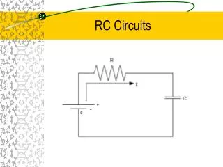
Charging a Capacitor • Consider a series circuit containing a resistor and a capacitor that is initially uncharged. • With switch S open, there is no current in the circuit. • When switch S is closed at t = 0 s, charges begin to flow and a current is present in the circuit and the capacitor begins to charge.
Charging a Capacitor • The gap between the capacitor plates represents an open circuit and charge does not pass from the positive plate to the negative plate. • Charge is transferred from one plate to the other plate through the resistor, switch, and battery until the capacitor is fully charged. • The value of the maximum charge depends on the EMF of the battery. • Once the maximum charge is reached, the current in the circuit is zero.
Charging a Capacitor • Applying Kirchhoff’s loop rule to the circuit after the switch is closed: • I ·R is the potential drop across the resistor. • q/C is the potential drop across the capacitor. • I and q are instantaneous values of the current and charge as the capacitor charges.
Charging a Capacitor • At t = 0 s, when the switch is closed, the charge on the capacitor is 0 C and the initial current is: • At t = 0 s, the potential drop is entirely across the resistor. • As the capacitor is charged to its maximum value Q, the charges quit flowing and the current in the circuit is 0 A and the potential drop is entirely across the capacitor.
Charging a Capacitor • Maximum charge: • From t = 0 s until the capacitor is fully charged and the current stops, the amount of current in the circuit decreases over time and the amount of charge on the capacitor increases over time. • To determine values for the current in the circuit and for the charge on the capacitor as functions of time, we have to use a differential equation.
Charging a Capacitor – Current Equation • Beginning with Kirchhoff’s loop equation, differentiate the equation with respect to time:
Charging a Capacitor – Current Equation • Replace dq/dt with I: • Get the current terms on one side of the equation and the other terms on the other side of the equation: • Integrate both sides of the equation.
Charging a Capacitor – Current Equation • The limits of integration for the current side of the equation is from Imax (at t = 0 s) to the current value at time t. • The limits of integration for the time side of the equation is from t = 0 s to time t.
Charging a Capacitor – Current Equation • Left side: • Right side:
Charging a Capacitor – Current Equation • Combining both sides of the integration: • To eliminate the natural log term (ln), we can use the terms as exponents for the base e. From the properties of logarithms:
Charging a Capacitor – Current Equation • Current in an RC circuit as a function of time: • Graph of Current vs. time for a charging capacitor:
Charging a Capacitor – Charge Equation • To find the charge on the capacitor as a function of time, begin with Kirchhoff’s loop equation: • Replace I with dq/dt:
Charging a Capacitor – Charge Equation • Get the dq/dt term on one side of the equation: • Divide both sides by R to solve for dq/dt: • Common demominator, R·C:
Charging a Capacitor – Charge Equation • Multiply both sides by dt: • Divide both sides by E·C-q to get the charge terms together on the same side of the equation: • In problems involving capacitance, q is positive, so multiply both sides by –1 to make the charge positive:
Charging a Capacitor – Charge Equation • Integrate both sides of the resulting differential equation. • For the charge side of the equation, the limits of integration are from q = 0 at t = 0 s to q at time t. I rearranged the equation to put the positive q first followed by the negative E·C. • For the time side of the equation, the limits of integration are from 0 s to t.
Charging a Capacitor – Charge Equation • Left side: • Right side:
Charging a Capacitor – Charge Equation • Combining both sides of the integrals: • To eliminate the natural log term (ln), we can use the terms as exponents for the base e.
Charging a Capacitor – Charge Equation • Simplify: • Solve for q: • Multiply both sides by –E·C. • Add E·C to both sides. • Factor out the E·C:
Charging a Capacitor – Charge Equation • Substitute: Qmax = E·C • Graph of Charge vs. time for a charging capacitor:
Current has its maximum value of I max = E/R at t = 0 s and decays exponentially to 0 A as t infinity. Charging A Capacitor
The charge on a capacitor is 0 C at t = 0 s and approaches a maximum value of Qmax = C·E as t infinity. Charging A Capacitor
Charging Capacitor Graphs current voltage charge
Time Constant R·C • The quantity R·C, which appears in the exponential component of the charge and current equations is called the time constant t of the circuit. • The time constant is a measure of how quickly the capacitor becomes charged. • The time constant represents the time it takes the: • current to decrease to 1/e of its initial value. • charge to increase from 0 C to C·E·(1-e-1) = 0.63·C·E. • The unit for the time constant is seconds. Ω · F = (V/A)(C/V) = C/(C/s) = s
q Qmax Capacitor Capacitor i Rise in Charge I 0.37 I Current Decay Time, t t 0.63 I Time, t t Charge and Current during the Charging of a Capacitor In a time t of one time constant, the chargeq rises to63%of its maximum, while the currenti decays to 37%of its maximum value.
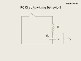
Discharging a Capacitor • Removing the battery from the circuit while keeping the switch open leaves us with a circuit containing only a charged capacitor and a resistor.
Discharging a Capacitor • When the switch is open, there is a potential difference of Q/C across the capacitor and 0 V across the resistor since I = 0 A. • If the switch is closed at time t = 0 s, the capacitor begins to discharge through the resistor and a current flows through the circuit. • At some time during the discharge, current in the circuit is I and the charge on the capacitor is q.
Discharging a Capacitor – Charge Equation • To find the charge on the capacitor as a function of time, begin with Kirchhoff’s loop equation. There is no E term in the equation because the battery has been removed. The I·R term is negative because the energy carried by the charges is dissipated in the resistor.
Discharging a Capacitor – Charge Equation • Replace I with -dq/dt because the current in the circuit is decreasing as the capacitor discharges over time: • Get the charge terms on one side of the equation and the remaining variables on the other side of the equation.
Discharging a Capacitor – Charge Equation • Integrate both sides of the resulting differential equation. • For the charge side of the equation, the limits of integration are from q = Qmax at t = 0 s to q at time t. • For the time side of the equation, the limits of integration are from 0 s to t.
Discharging a Capacitor – Charge Equation • Left side: • Right side:
Discharging a Capacitor – Charge Equation • Combining both sides of the integrals: • To eliminate the natural log term (ln), we can use the terms as exponents for the base e.
Discharging a Capacitor – Charge Equation • Simplify: • Solve for q:
Discharging a Capacitor – Current Equation • To find the current on the capacitor as a function of time, begin with the charge equation. • Current I = dq/dt, so take the derivative of the charge equation with respect to time:
Discharging a Capacitor – Current Equation • Left side: • Right side:
Discharging a Capacitor – Current Equation • Combining the two sides of the integral: • Qmax = C·V, substituting:
Discharging a Capacitor – Current Equation • The negative sign indicates that the direction of the discharging current is opposite to the direction of the charging current. • The voltage V across the capacitor is equal to the EMF of the battery since the capacitor is fully charged at the time of the switch is closed to discharge the capacitor through the resistor.
Discharging Capacitor Graphs voltage charge current
Bonus Equations! • I have never seen these equations in any textbook and had never been asked to find the voltage across the capacitor as a function of time. I got these equations from the E & M course I took Fall 06. • Discharging Capacitor:
Bonus Equations! • Charging Capacitor:
Energy Conservation in Charging a Capacitor • During the charging process, a total charge Q = EC flows thru the battery. • The battery does work W = QmaxE or W = CE2. • Half of this work is accounted for by the energy stored in the capacitor: U = 0.5QV = 0.5QmaxE = 0.5CE2 • The other half of the work done by the battery goes into Joule heat in the resistance of the circuit.
The rate at which energy is put into the resistance R is: • Using the equation for current in a charging capacitor: • Determine the total Joule heat by integrating from t = 0 s to t = :
The result is independent of the resistance R; when a capacitor is charged by a battery with a constant EMF, half the energy provided by the battery is stored in the capacitor and half goes into thermal energy. • The thermal energy includes the energy that goes into the internal resistance of the battery.
Capacitors and Resistors in Parallel • The capacitor in the figure is initially uncharged when the switch S is closed. • Immediately after the switch is closed, the potential is the same at points c and d.
An uncharged capacitor does not resist the flow of current and acts like a wire. • No current flows thru the 8 Ωresistor; the capacitor acts as a short circuit between points c and d. • Apply Kirchhoff’s loop rule to the outer loop abcdefa: 12 V – 4 Ω·I0 = 0; I0 = 3 A
After the capacitor is fully charged, no more charge flows onto or off of the plates; the capacitor acts like a broken wire or open in the circuit. • Apply Kirchhoff’s loop rule to loop abefa: 12 V – 4 Ω·If– 8 Ω·If = 0; 12 V – 12 Ω·If; If = 1 A
RC Circit Problem Example • You will see this problem on your homework.