Download

1 / 15
180 likes | 325 Views
Enhanced Counter Air Projectile “A Smart Bullet Concept”. Study Project for MAE 659 Advanced Aerospace Design. Presented by Bill Nourse 876-7384 bill.nourse@rdec.redstone.army.mil. 29 Aug 2003. ECAP Problem Statement.

E N D
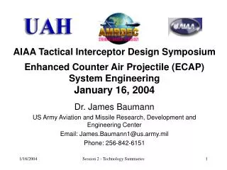
Enhanced Counter Air Projectile “A Smart Bullet Concept” Study Project for MAE 659 Advanced Aerospace Design Presented by Bill Nourse 876-7384 bill.nourse@rdec.redstone.army.mil 29 Aug 2003
ECAP Problem Statement • No Existing or Programmed System With a Capability to Negate Rockets and Mortar/Artillery Projectiles With Mechanical Fuzes After They Are Launched • No Existing Capability Against Saturation Attack • Need for More Cost-effective Solutions
ECAP Threat Target Set • The ECAP Aerial Threat Target Set Consists of: • Primary • Rocket, Artillery, Mortar (RAM) Projectiles • Large Caliber Rockets (LCR) • Secondary • UAV • Land Attack Cruise Missiles (LACM) • Rotary-Wing (RW)
ECAP Required Capabilities • Required Capabilities Include: • The Ability to Kill Rocket, Artillery and Mortar Projectiles in Flight Between 2 and 4 Kilometers From Launch Point • The Ability to Engage Multiple Incoming Projectiles From Same Launch Platform - Saturation Attack
Variety of Sensors UAV ECAP Concept of Operation Rockets Artillery/Mortars RW Guided Projectile Fire Control Radar Launch Platform/ Gun System 500m 2km 4km
ECAP Study Objectives • Investigate Feasibility of Employing Guided Projectile to Engage and Defeat Identified Threat • Nominally the Guided Projectile is a Gun Launched 40mm Projectile • Evaluate Alternate Schemes for Guiding the Projectile • Guidance • Controls • Aerodynamics • Packaging • Propulsion Augmentation • Recommend Best Technical Approach for Further Development
ECAP Study Objectives (cont.) • Develop and Mature a Concept Description Document (CDD) • Contains Project Requirements • UAH Project Office is Responsible for Developing, Refining, and Maintaining the CDD Under the Customer’s Direction • The CDD Will be Drafted and Refined in Phase 0 Through Iterations Between UAH Project Office and Customer • Data Generated by the Study Team Will be Used to Support the Development and Refinement of the CDD
ECAP Trajectory Dispersions • Trajectory Dispersions Result From Errors Induced by the Launcher/Gun, Environment, Sensors, and the Projectile and It’s Components • These Error Sources Include: • Aiming Errors (Azimuth and Elevation) • Tip-Off Errors • Mass Asymmetries (Round-to-Round) • Aerodynamic Asymmetries and Uncertainties (Round-to-Round) • Environmental Factors • Inertial Sensor Errors • Spin Rate Variations • Variances in Initial Velocity
ECAP Trajectory Dispersions (cont.) • Environmental Factors Include Air Density, Wind and Temperature • The ECAP Guided Projectile Must be Able to Function Effectively in Winds Up to 5.0 m/s (1-sigma) From Any Direction • Initial Velocity Errors Are Caused by Variability of Muzzle Velocities (Round-to-Round) and Will Vary the Projectile Time of Flight to the Planned Intercept Point • Aiming Errors Are Caused by Angle Variations in Azimuth and Elevation • Tip-Off Errors Occur When Forces Are Imparted on the Projectile by the Barrel Due to Structural and Recoil Effects • High Spin Rates Encourage Stability But Can Also Affect Inertial Sensor Errors and Control Issues • Aerodynamic and Mass Asymmetries Are Caused by Round-to-Round Variation in Projectile Shape and Mass
ECAP Technologies • Controls • The Control System Must Provide the Required Divert Capability to Remove Weapon System Errors, Target Uncertainties, and Target Maneuvers • Packaging Considerations Key Driver • Possible Control Schemes Include: Mini-Canards, Piezo-Electric Fins, MEMS Thrusters, Moving Masses, Etc. • Guidance • The Guidance System Must Provide Adequate Information to Drive Control System to Remove Errors • Includes Sensors and Guidance Laws
ECAP Technologies (cont.) • Possible Guidance Schemes Include: • Command Guidance • Semi-Active Guidance • Radar • Laser • Passive Guidance • Infrared • Guidance Laws Generate Missile Acceleration Commands That are Used by the Interceptor to Guide to Target • Guidance Laws for Consideration Include: Proportional Navigation, Zero Effort Miss, Line-of-Sight, and Beam Rider
ECAP Technologies (cont.) • Drag and Packaging • The Projectile Should be Designed to Minimize Drag But Still Provide Adequate Packaging Volume for Required Components • Spin Rate • High Spin Rates Encourage Stability But Can Affect Inertial Sensor Performance and Reduce Control System Effectiveness • A Balance Between Stability, Inertial Senor Performance and Controllability Should Be Found
ECAP Study Results • The Customer Will Be Conducting Independent, Parallel Studies • The Results of the UAH ECAP Study Effort Will be Used by the Customer to Augment, Extend, and Stimulate His Own Studies • The Customer Will Continue to Provide Guidance and Share the Results of His Studies as They Emerge
Discipline Description Personnel Phone E-Mail* Project Office Coordinator Christina Davis 313-0212 christina.davis@ Systems Engineering Mentor Dr. Jim Baumann 842-6151 james.baumann@ Propulsion Mentor Dr. Jay Lilley 876-3225 jay.lilley@ Aerodynamics Mentor Lamar Auman 876-4798 lamar.auman@ Systems Simulation Mentor George Sanders 876-2301 george.sanders@ Guidance and Control Mentor Mark Dixon 876-5935 mark.dixon@ Seeker Mentor Jim English 842-9347 jame.english@ Engineering Analysis Mentor TBD Prototyping Mentor Jim Pope 876-7892 jim.pope@ ECAP Mentors *e-mail extension common to all is rdec.redstone.army.mil
Transforming the Force—From Korea to Today Major General (Retired) Robert H. Scales, Jr. Historian and Former Commandant of the Army War College, Carlisle Barracks, Pennsylvania Quote From Field Artillery, July-August 2001 “Another fact: historically in limited liability wars, most Americans killed in combat were killed by rudimentary weapons; the greatest killer of Americans on the battlefield is the mortar. A distant second is automatic weapons. Mines are a very distant third. I think the historical pattern will continue: Most Americans killed in combat will die from the effects of simple weapons while facing an enemy fighting on equal terms in the close fight. That was true for the Russians in Afghanistan, and it is true for the Israelis today. One of the ironies today is that a B-2 bomber can fly 8,000 miles to destroy a building with one bomb from a safe distance, yet a platoon under mortar fire is relatively helpless.”