Download
1 / 22
390 likes | 1.08k Views
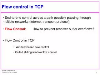
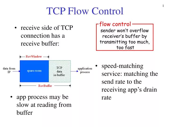
receive side of TCP connection has a receive buffer:. speed-matching service: matching the send rate to the receiving app’s drain rate. TCP Flow Control. flow control. sender won’t overflow receiver’s buffer by transmitting too much, too fast.

E N D
receive side of TCP connection has a receive buffer: speed-matching service: matching the send rate to the receiving app’s drain rate TCP Flow Control flow control sender won’t overflow receiver’s buffer by transmitting too much, too fast • app process may be slow at reading from buffer
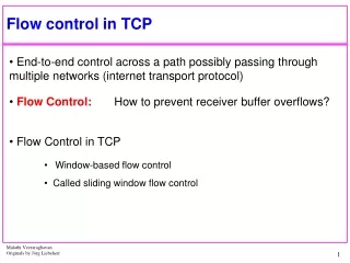
(Suppose TCP receiver discards out-of-order segments) spare room in buffer = RcvWindow = RcvBuffer-[LastByteRcvd - LastByteRead] Rcvr advertises spare room by including value of RcvWindow in segments Sender limits unACKed data to RcvWindow guarantees receive buffer doesn’t overflow TCP Flow control: how it works
More • Slow receiver • Ack new window • Persist timer • Long fat pipeline: high speed link and/or long RTT • Window scale option during handshaking
Header 32 bits source port # dest port # sequence number acknowledgement number head len not used Receive window U A P R S F checksum Urg data pnter Options (variable length) application data (variable length)
Congestion: informally: “too many sources sending too much data too fast for network to handle” different from flow control! manifestations: lost packets (buffer overflow at routers) long delays (queueing in router buffers) a top-10 problem! Principles of Congestion Control
two senders, two receivers one router, infinite buffers no retransmission large delays when congested maximum achievable throughput Causes/costs of congestion: scenario 1 lout lin : original data unlimited shared output link buffers Host A Host B
one router, finite buffers sender retransmission of lost packet Causes/costs of congestion: scenario 2 Host A lout lin : original data l'in : original data, plus retransmitted data Host B finite shared output link buffers • “costs” of congestion: • more work (retrans) for given “goodput” • unneeded retransmissions: link carries multiple copies of pkt
four senders multihop paths timeout/retransmit Causes/costs of congestion: scenario 3 l l in in Host A Host B Q:what happens as and increase ? lout lin : original data l'in : original data, plus retransmitted data finite shared output link buffers
Causes/costs of congestion: scenario 3 Host A Host B lout Another “cost” of congestion: • when packet dropped, any “upstream transmission capacity used for that packet was wasted!
End-end congestion control: no explicit feedback from network congestion inferred from end-system observed loss, delay approach taken by TCP Network-assisted congestion control: routers provide feedback to end systems single bit indicating congestion (SNA, DECbit, TCP/IP ECN, ATM) explicit rate sender should send at Approaches towards congestion control Two broad approaches towards congestion control:
ABR: available bit rate: “elastic service” if sender’s path “underloaded”: sender should use available bandwidth if sender’s path congested: sender throttled to minimum guaranteed rate RM (resource management) cells: sent by sender, interspersed with data cells bits in RM cell set by switches (“network-assisted”) NI bit: no increase in rate (mild congestion) CI bit: congestion indication RM cells returned to sender by receiver, with bits intact Case study: ATM ABR congestion control
two-byte ER (explicit rate) field in RM cell congested switch may lower ER value in cell sender’ send rate thus minimum supportable rate on path EFCI bit in data cells: set to 1 in congested switch if data cell preceding RM cell has EFCI set, sender sets CI bit in returned RM cell Case study: ATM ABR congestion control
Transport-layer services Multiplexing and demultiplexing Connectionless transport: UDP Principles of reliable data transfer Connection-oriented transport: TCP segment structure reliable data transfer flow control connection management Principles of congestion control TCP congestion control Outline
end-end control (no network assistance) sender limits transmission: LastByteSent-LastByteAcked cwnd Roughly, cwnd is dynamic, function of perceived network congestion How does sender perceive congestion? loss event = timeout or 3 duplicate acks TCP sender reduces rate (cwnd) after loss event mechanisms: slow start congestion avoidance AIMD TCP Congestion Control cwnd rate = Bytes/sec RTT
When connection begins, cwnd = 1 MSS Example: MSS = 500 bytes & RTT = 200 msec initial rate = 20 kbps available bandwidth may be >> MSS/RTT desirable to quickly ramp up to respectable rate TCP Slow Start • When connection begins, increase rate exponentially fast until first loss event
When connection begins, increase rate exponentially until first loss event: incrementing cwnd for every ACK received double cwnd every RTT Summary: initial rate is slow but ramps up exponentially fast TCP Slow Start (more) Host A Host B one segment RTT two segments four segments time
Congestion Avoidance • ssthresh: when cwnd reaches ssthresh, congestion avoidance begins • Congestion avoidance: increase cwnd by 1/cwnd each time an ACK is received • Congestion happens: ssthresh=max(2MSS, cwnd/2)
multiplicative decrease: cut cwnd in half after loss event TCP AIMD additive increase: increase cwnd by 1 MSS every RTT in the absence of loss events: probing Long-lived TCP connection
After 3 dup ACKs: cwnd is cut in half window then grows linearly But after timeout event: cwnd instead set to 1 MSS; window then grows exponentially to a sshthresh, then grows linearly Reno vs. Tahoe Philosophy: • 3 dup ACKs indicates network capable of delivering some segments • timeout before 3 dup ACKs is “more alarming”
Summary: TCP Congestion Control • When cwnd is below sshthresh, sender in slow-start phase, window grows exponentially. • When cwnd is above sshthresh, sender is in congestion-avoidance phase, window grows linearly. • When a triple duplicate ACK occurs, sshthresh set to cwnd/2 and cwnd set to sshthresh. • When timeout occurs, sshthresh set to cwnd/2 and cwnd is set to 1 MSS.
Trend • Recent research proposes network-assisted congestion control: active queue management • ECN: explicit congestion notification • 2 bits: 6 &7 in the IP TOS field • RED: random early detection • Implicit • Can be adapted to explicit methods by marking instead of dropping