Download
1 / 22
220 likes | 320 Views
Companding in DSPs. Ari Klein Research Adviser: Professor Yannis Tsividis. PROBLEM WITH SMALL SIGNALS. ADC Transfer function. output. Does not take full advantage of available bits A lot of distortion in output. input. ADVANTAGE OF LARGE SIGNALS. ADC Transfer function. output.

E N D
Companding in DSPs Ari Klein Research Adviser: Professor Yannis Tsividis
PROBLEM WITH SMALL SIGNALS ADC Transfer function output • Does not take full advantage of available bits • A lot of distortion in output input
ADVANTAGE OF LARGE SIGNALS ADC Transfer function output • Takes full advantage of available bits • Much less distortion input
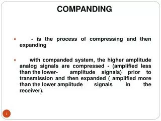
COMPANDING Input D.R. Output D.R. Digital System compress expand
X X ADC DAC If there is only an ADC and a DAC (no DSP in between): input output 1/g(n) = env(n) g(n) = 1/env(n)
X X ADC DSP DAC What about with a DSP between the ADC and DAC? Might consider: input output g(n) 1/g(n) BUT THIS SCHEME WILL NOT WORK SINCE IT HORRIBLY DISTORTS THE INPUT/OUTPUT BEHAVIOR IN GENERAL
( ( ) ) g(n-k) g(n-k) X X ADC Z-k DAC g(n) g(n) K-sample delay: y(n)=u(n-k) If I try: u(n) y(n) g(n) g(n-k)*u(n-k) 1/g(n) u(n-k) So y(n) = u(n-k) X • The output is DISTORTED by the factor • This is a time-varying distortion. • More complicated systems will have more complicated distortions
The Problem: Get input, output and states which always have large envelopes Given a system whose input u, output y, and state vector x are related by: x(n+1) = Ax(n) + Bu(n) y(n) = Cx(n) + Du(n) Construct a modified system whose input um, output ym, and state vector xmalways have large envelopes, andare related by: xm(n+1) = Am(n)xm(n) + Bm(n)um(n) ym(n) = Cm(n)xm(n) + Dm(n)um(n) • Choose a relationship between xm,um,ym and x,u,y • Find the corresponding relationship between Am,Bm,Cm,Dm and A,B,C,D
One Solution • um(n) = u(n)/e(u(n)) • ym(n) = y(n)/e(y(n)) • xm(n) = x(n)/e(x(n)) xm(n+1) = Am(n)xm(n) + Bm(n)um(n) ym(n) = Cm(n)xm(n) + Dm(n)um(n) The elements of Am, Bm, Cm, andDm are then related to the elements of A, B, C and D by: am(n,i,j) = a(i,j)*[e(xj(n))/e(xi(n+1))] bm(n,i) = b(i)*[e(u(n))/e(xi(n+1))] cm(n,j) = c(j)*[e(xj(n))/e(y(n))] dm(n) = d*[e(u(n))/e(y(n))] Only RATIOS of envelopes are required.
Companding for DSPs / / ADC DSP DAC e-signals input output • This system is INTERNALLYTIME-VARYING • Its input/output behavior is IDENTICAL to the original system’s (in the absence of quantization) • It is therefore EXTERNALLY TIME-INVARIANT
Complete Companding System (conceptual):The e-signals are (roughly) the envelopes of the corresponding signals in the non-companding DSP ADC DSPC ADC delay DAC DAC DAC input output / x Envelope Detection DSP without companding Compute ratios
To date: I have simulated the conceptual companding system for the allpass digital reverberator shown below The results have been promising
Typical Results • Input • State in original system • Corresponding state in companding system • Output of original system • Output of I/O companding system with no internal correction • Output of properly companding system
Measuring the improvements quantitatively “Steady-State” case • But I would really like to consider the transient case. The problems are: • What should the input be? • What should be measured and compared at the output to quantify the inprovements? (SNDR is not necessarily the best choice) • When (and over how long an interval) should I take these measurements?
Work in Progress: • Improving Efficiency: • Constraining the e-signals to be powers of two : • Easier to process and store • Multiplications become shifts • Division (computing ratios) becomes subtraction • Errors due to additional “quantization” of e-signals offset by elimination of division errors • Similar to floating point! • Lowpass filtering the e-signals • Envelopes should be relatively slowly varying, so can LPF without too much loss of information • Once LPF, can downsample – potentially MUCH less computation • But must still ensure that envelope always greater than signal to avoid overflow – HOW?
A single-ADC solution • Clocked at twice the sampling rate to avoid algebraic loop
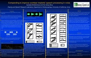
Possible Improvement: Masking • With companding, get most noise when signals are large • Suggests that should take advantage of MASKING: Noise Threshold In Presence of Signal Noise Threshold In Quiet f f • The noise threshold is raised for frequencies near a signal • A significant amount of the noise that is in frequencies close to a large signal is below threshold and perceptually inaudible – it is masked by the signal
To take advantage of this: Use a bank of bandpass filters BPF BPF BPF BPF DSP BPF BPF BPF BPF
Theoretical Considerations Already Proven: Companding does not change the original system’s • Stability • Controllability • Observability Would like to find: • General method for easily implementing companding • The “optimal” e-signals for minimizing quantization errors • Upper bound on performance improvement due to companding • General description of the type of systems where companding is most useful
Open Questions • All measurements shown were in the time domain. To measure in the frequency domain, what input frequency should I use (as a function of the sampling rate), and how many points should be used for the FFT? • I would really like to get quantitative measurements for the transient case. The problems are: • What should the input be? • What should be measured and compared at the output to quantify the improvements? (SNDR is not necessarily the best choice) • When (and over how long an interval) should I take these measurements? • Any ideas how to resolve the algebraic loop in the single-ADC architecture without doubling the sampling rate? • I want to LPF/downsample the env det output. How can I still ensure that it stays above the signal, so that the companded signals don’t overflow? • Even better would be to have LPF/downsample before the original system, to reduce processing. Is this equivalent (even roughly) to LPF at output of env det?
Hardware I have succeeded in getting a complete companding system to work on the TI 6713 floating point DSP in real-time. The “analog” parts “run” in floating-point. The digital parts “run” in 8-bit fixed point. I used Simulink’s Real Time Workshop and Embedded Link to automatically generate the code. I then edited it to make it more efficient. It is still very inefficient. It only runs in real-time at 22.05kHz (I downsample the input) Eventually, I want to have an efficient fixed point implementation running at 44.01kHz on a fixed-point DSP in real-time, with the analog parts actually implemented with analog circuits.