Download
1 / 12
120 likes | 135 Views
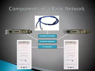
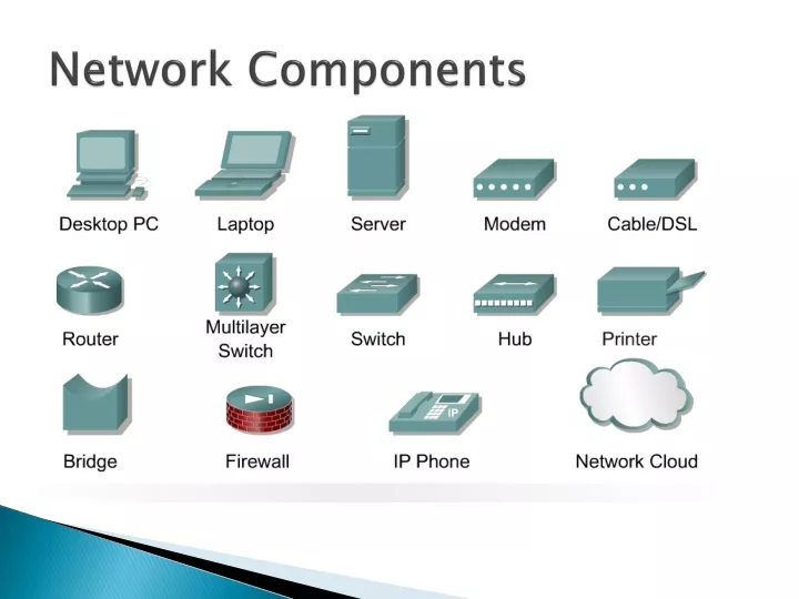
Network Components. Switches. Switches operate at the Data Link layer (layer 2) of the OSI model Can interpret address information Switches resemble bridges and can be considered as multiport bridges.

E N D
Switches • Switches operate at the Data Link layer (layer 2) of the OSI model • Can interpret address information • Switches resemble bridges and can be considered as multiport bridges • By having multiports, can better use limited bandwidth and prove more cost-effective than bridge Cisco Catalyst 2900 switch
Switches divide a network into several isolated channels • Packets sending from 1 channel will not go to another if not specify • Each channel has its own capacity and need not be shared with other channels Hub 3.3Mbps 10Mbps 3.3Mbps Switch 3.3Mbps 10Mbps 10Mbps 10Mbps
Advantages of Switches • Switches divide a network into several isolated channels (or collision domains) • Reduce the possibility of collision • Collision only occurs when two devices try to get access to one channel • Can be solved by buffering one of them for later access • Each channel has its own network capacity • Suitable for real-time applications, e.g. video conferencing • Since isolated, hence secure • Data will only go to the destination, but notothers
Limitations of Switches • Although contains buffers to accommodate bursts of traffic, can become overwhelmed by heavy traffic • Device cannot detect collision when buffer full • CSMA/CD scheme will not work since the data channels are isolated, not the case as in Ethernet • Some higher level protocols do not detect error • E.g. UDP • Those data packets are continuously pumped to the switch and introduce more problems
Routers • Layer 2 Switches cannot take advantage of multiple paths • Routers work at the OSI layer 3 (network layer) • They use the “logical address” of packets and routing tables to determine the best path for data delivery
How Routers Work • As packets are passed from routers to routers, Data Link layer source and destination addresses are stripped off and then recreated • Enables a router to route a packet from a TCP/IP Ethernet network to a TCP/IP token ring network • Only packets with known network addresses will be passed - hence reduce traffic • Routers can listen to a network and identify its busiest part • Will select the most cost effective path for transmitting packets
How Routing Table is formed • Routing table is formed based on communications between routers using “Routing Protocols” • Routing Protocols Routable Protocol • Routing Protocols collect data about current network status and contribute to selection of the best path Routers communicate within themselves
Routing Protocol Example - RIP for IP Routing • RIP (Routing Information Protocol) ― the oldest one • Use no. of hops between nodes to determine best path • Does not consider the network congestion condition • Broadcast every 30 sec the routing table to neighbouring routers to convey routing information • RIP is limited to interpreting a maximum of 16 hops • Not suitable for large network (e.g. Internet) • Can create excessive network traffic due to broadcasting • May take a long time to reach the far reaches