Download
1 / 51
530 likes | 712 Views
Training Module MAIN MENU. Click to Select a Training Module Topic Digital MultiMeters Clamp Meters Tachometers IR Tachometers. Digital MultiMeter Training Module. March 2009 Rev. 1.2. What is a Digital MultiMeter.

E N D
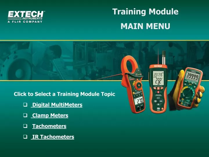
Training Module MAIN MENU • Click to Select a Training Module Topic • Digital MultiMeters • Clamp Meters • Tachometers • IR Tachometers
Digital MultiMeter Training Module March 2009 Rev. 1.2
What is a Digital MultiMeter A Digital MultiMeter (or DMM) is an instrument capable of performing a number of measurement functions and displaying the results digitally The basic functions that most meters offer are Voltage, Current, Resistance, Diode, and Continuity Some DMMs offer more advanced functions such as Capacitance, Frequency, Power, and Temperature
How are Digital MultiMeters used To perform tests, meters are connected to circuits, components, and other devices via 'test leads' Test leads are insulated wire probes that plug directly into the meter Dials or switches on the meter allow the user to select the measurement function and other modes of operation Display icons inform the user as to the unit of measure, range, resolution and other useful information
Auto Range and Manual Range Meters On a Manual Range meter, the user must select the measurement range using a selector switch or rotary dial An Auto Range instrument automatically selects the optimum range and display resolution Auto Range meters have the added benefit of allowing Manual Range operation if and when desired
0V 60 120 180 240V Range Measurement Range For a given measurement function, the range refers to the span between the highest and lowest possible meter readings. For example, in the AC voltage mode, a range of 0 to 240VAC means that a measurement of 120VAC is possible because it falls in the “range” of the meters capability
Measurement Resolution For a given measurement function, the resolution refers to how finely a meter reading can be expressed. For example, when measuring AC voltage, if the meter’s resolution is 1 volt, a measurement of 120 VAC would display as 120VAC. However, for a resolution of 0.1 the reading would be expressed as 120.0 VAC providing a tenth of a volt ‘resolution’ 120 V = 1 volt resolution 120.0 V = 0.1 (tenth of a volt) resolution
True RMS vs. Average Responding Meters An Average Responding meter measures AC signals by averaging the peaks and valleys of a waveform; This is perfectly acceptable for periodic, distortion-free sinusoidal signals However, for non-periodic, noisy, & distorted waveforms a True RMS meter is needed if high accuracy is required True RMS is a ROOT MEAN SQUARE function that maps instantaneous points along a waveform leading to an accurate measurement value
Safety Rating Categories • Hazardous transients and spikes can occur during measurements • In order to shield the user, meters are outfitted with one of four protection levels known as Category Ratings (CAT I, II, III, IV) • The higher the CAT number, the higher the transient protection • The user selects a Category of meter that is appropriate for the area where the testing is to be performed • For example, working with 3 phase motors, variable speed drives, 277V lighting circuits, or distribution panels requires Cat III meters
Safety Rating Category Guidelines CAT IV - 3 phase at utility connection - Outdoor conductors CAT III - 3 Phase Distribution - Commercial lighting CAT II Single Phase receptable connected loads CAT I Electronic Circuits
Voltage Safety Ratings In addition to Category Ratings, MultiMeters have Voltage ratings For example, CAT II – 600V or CAT III - 1000V Confusion can arise from these safety conventions. A CAT II – 1000V does not offer more protection than a CAT III – 600V meter Always refer to the CAT rating first and then the voltage rating
Extech EX300 Series • Mini Digital MultiMeters + AC Voltage Detector • Large Digits for easy viewing • LED indicator & audible tone for Volt Detector • Manual or Auto Range Models • Thermometer, Capacitor, and Frequency Models
Extech EX400 Professional Series • Non-contact IR Thermometers on select models • Large Backlit Display • True RMS on select models • Auto Range on select models • Low Current Measurement Capability • Input Fuse Protection • Incorrect Connection Warnings • Capacitance, Frequency, Frequency on select models
Extech EX500 Heavy Duty Industrial Series • Water proof design • Double molded • 1000V protection – all functions • Large Backlit LCD • True RMS models • 4,000, 6,000, and 40,000 display count models • Bargraph on select models Back to Main Menu
Clamp Meter Training Module March 2009 Rev. 1.1
What is a Clamp Meter A Clamp Meter is an instrument capable of measuring AC or DC Current by clamping around a single conductor and displaying the results digitally Clamp meters oftentimes have Digital MultiMeter functions built in such as Voltage and Resistance The area of the meter that clamps onto the conductor is known as the ‘jaw’ and is opened by the user with a press of a button
Clamp Meters continued A clamp meter is a safe, convenient, and efficient way to measure current without having to use test leads Since current flow through a conductor causes a magnetic field, the clamp meter can sense this field and provide a corresponding current reading (in amperes or amps) Clamp meters do not interrupt current flow thereby allowing the technician to make the measurement quickly and safely.
How are Clamp Meters used To perform tests the meter is clamped around a single conductor using the clamp jaw Dials or switches on the meter allow the user to select the range and other modes of operation Display icons convey the unit of measure, range, resolution and other useful information If a cable run includes more than one conductor It must be modified to allow access to only one conductor at a time
AC Line Separator An AC Line Separator or 'Splitter' allows the user to isolate a single conductor from a multi-conductor cable safely, easily, and without the need for splicing wires manually.
Auto Range and Manual Range Clamp Meters On a Manual Range meter, the user must select the measurement range using a selector switch or rotary dial An Auto Range instrument automatically selects the optimum range and display resolution Auto Range meters have the added benefit of allowing Manual Range operation if and when desired
0A 10 20 30 40A Range Measurement Range The range refers to the span between the highest and lowest possible meter readings. For example, in the AC Current mode, a range of 0 to 40 Amperes means that a measurement of 20A is possible because it falls in the meter's 'range'
Measurement Resolution For a given measurement function, the resolution refers to how finely a meter reading can be expressed. For example, when measuring AC Current, if the meter’s resolution is 1 amp, a measurement of 20 amps would display as 20. However, for a resolution of 0.1 the reading would be expressed as 20.0 providing a tenth of a volt ‘resolution’ 20 A = 1 Amp resolution 20.0 = 0.1 (tenth of a Amp) resolution
True RMS vs. Average Responding Meters An Average Responding meter measures AC signals by averaging the peaks and valleys of a waveform; This is perfectly acceptable for periodic, distortion-free sinusoidal signals However, for non-periodic, noisy, & distorted waveforms a True RMS meter is needed if high accuracy is required True RMS is a ROOT MEAN SQUARE function that maps instantaneous points along a waveform leading to an accurate measurement value
Safety Rating Categories • Hazardous transients and spikes can occur during measurements • In order to shield the user, meters are outfitted with one of four protection levels known as Category Ratings (CAT I, II, III, IV) • The higher the CAT number, the higher the transient protection • The user selects a Category of meter that is appropriate for the area where the testing is to be performed • For example, working with 3 phase motors, variable speed drives, 277V lighting circuits, or distribution panels requires Cat III meters
Safety Rating Category Guidelines CAT IV - 3 phase at utility connection - Outdoor conductors CAT III - 3 Phase Distribution - Commercial lighting CAT II Single Phase receptable connected loads CAT I Electronic Circuits
Voltage Safety Ratings In addition to Category Ratings, MultiMeters have Voltage ratings For example, CAT II – 600V or CAT III - 1000V Confusion can arise from these safety conventions. A CAT II – 1000V does not offer more protection than a CAT III – 600V meter Always refer to the CAT rating first and then the voltage rating
Extech EX800 Series • 1000 Amp Clamp Meters with IR Thermometer • True RMS Current / Voltage on select models • DMM functions include Voltage, Resistance, • Capacitance, Frequency, Diode, and Continuity • Auto Range • 1.7" Clamp Jaw Opening
Extech EX700 Double Molded Series • 800 AC Amp Clamp Meters with Type K Thermometer • on select models • DC Current on Model EX730 • True RMS Current / Voltage on select models • DMM functions include Voltage, Resistance, • Capacitance, Frequency, Diode, and Continuity • Auto Range • 1.2" Clamp Jaw Opening
Extech EX600 Series • 400A Dual Input Clamp Meters with IR • Thermometer and Non-contact volt detector • True RMS for AC Voltage / Current • Non-contact voltage detector offers LED alert • 40,000 display counts for DMM functions • DMM functions include Voltage, Resistance, • Capacitance, and Frequency • 1.4" Clamp Jaw Opening Back to Main Menu
Tachometer Training Module March 2009 Rev. 1.0
What is a Tachometer A tachometer measures the angular speed of a rotating shaft in revolutions per minute (RPM) A good example is a rotating fan blade Some tachometers can measure linear surface speed in terms of feet (or meters) per minute For example, a conveyor belt or escalator hand-rail
Contact Tachometers The tip of the Contact Tachometer's sensor is place in direct contact with a moving object in order to obtain a measurement reading The sensor tip can be fitted with a wheel or other supplied attachment for contacting shafts, belts, and other moving objects Use a contact tachometer for applications where direct contact of the tachometer with the object is preferred
Non-Contact Photo Tachometers Non-contact tachometers use light (photo) reflections to measure RPM A small square of reflective tape (approx. 1/4") is mounted on the object to be measured and the meter's light source is directed toward the tape The reflection from the tape allows the meter to display an accurate RPM reading
Combination Tachometers Combination tachometers support Contact and Non-Contact operation One end of the meter is a Photo Tachometer and the other is a Contact Tachometer The LCD display is typically reversible so that the user can switch from one mode of operation to the other and the display will automatic orient the displayed reading
Laser pointer feature A laser pointer allows the user to better aim the Photo Tachometer
InfraRed (IR) Thermometer Feature In addition to saving time and cutting cost, the built-in IR thermometer can check for hot spots and scan surface temperature The IR thermometer permits non-contact temperature measurements for areas difficult to reach or unsafe to touch
Extech RPM10 • Combination Laser Tachometer • Built-in IR Thermometer • Fixed Emissivity 0.95 • 6:1 distance to spot ratio (IR) • Automatic Reversible Display
Extech 461920 • Mini Laser Photo Tachometer / Counter • Non-contact RPM Measurements • Count Measurements to 99,999 revolutions • Backlit 5-digit LCD display • Rugged double molded housing
Extech 461995 • Copmbination Contact / Laser Photo Tachometer • Non-contact and Contact Measurements • Reversible LCD display • Laser guided non contact measurements • Records last 5 readings Back to Main Menu
IR Thermometer Training Module March 2009 Rev. 1.0
What is an InfraRed (IR) Thermometer In Infrared or ‘IR’ Thermometer is an instrument that can remotely sense the temperature of a surface and display that temperature digitally The user simply points the meter, pulls the trigger, and reads the surface temperature
How does an IR Thermometer work An IR thermometer senses the infrared energy emitted by the surface under test All materials emit infrared energy and the amount of energy emitted is proportional to the temperature of the material The meter simply converts the infrared it collects into a temperature display
Advantages of an IR Thermometer Non-contact measurements are safe IR measurements are extremely fast IR Thermometers can measure moving objects IR thermometers can measure from a safe distance
What is ‘Field of View’ The field of view is the area that the meter's sensor encompasses This area changes size as the meter is moved closer or further away from the target In this way, the IR sensor beam behaves much like a flashlight The closer a flashlight is to a wall, the smaller the light spot; the further from the wall, the larger the spot
Diameter of Spot 2” 4” 1” 0.5” 6” 12” 24” 48” Distance to Object ‘Field of View’ continued The Field of view is governed by the meter's 'Distance to Spot ratio' If the D/S ratio of a given IR thermometer is 12:1, the spot will be a 1” diameter circle when the meter is held 12” from the surface
What is Emissivity Technical Definition Emissivity is defined as the ratio of the energy radiated by an object at a given temperature to the energy emitted by a perfect radiator, or blackbody, at the same temperature
More on Emissivity Emissivity is not a concern when the surface under test is coated by flat black paint (black body). Flat black is the highest emissivity However, in common practice, surfaces can be highly polished and very reflective. These are known as low emissivity surfaces. In these cases the IR thermometer can have difficulty obtaining an accurate reading. This is where Emissivity comes into play Many IR thermometers have an adjustable emissivity which compensates for low emissivity surface characteristics.
Emissivity Settings The emissivity of a blackbody is 1.0. The full emissivity range is 0.0 to 1.0. The lower the number, the more reflective the surface Some meters allow the user to set the emissivity to match the characteristics of the surface under test Other infrared thermometers have a fixed emissivity of 0.95 For very low emissivities, flat black paint or tape should be applied to the surface to effectively change the surface emissivity
Extech Model 42512 • Dual Laser IR Thermometer • Dual laser simplifies distance to target ratio • Exclusive 150ms temperature spike capture • Adjustable Emissivity • Adjust High-Low Temperature alerts • Double molded housing
Extech Model 42542 • High Temperature IR thermometer (1832 degrees F) • 30:1 D/S ratio • Adjustable High-Low Temperature Alerts • Adjustable emissivity • Large Backlit LCD • Laser point identifies target area