Download
1 / 11
110 likes | 241 Views
T owards Sensor Decision for ATLAS IBL. LHCC Upgrade session CERN, June, 14 th 2011 G. Darbo – INFN / Genova Indico agenda: https://indico.cern.ch/conferenceDisplay.py?confId= 141306. Sensors Designs for IBL. Not enough data available to make decision on sensors

E N D
Towards Sensor Decision for ATLAS IBL LHCC Upgrade session CERN, June, 14th 2011 G. Darbo – INFN / Genova Indico agenda: https://indico.cern.ch/conferenceDisplay.py?confId=141306
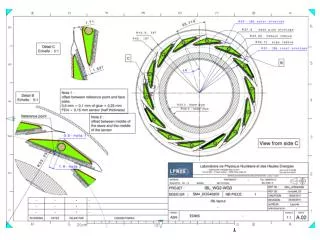
Sensors Designs for IBL • Not enough data available to make decision on sensors Planar: need more measurement with full radiation dose 3D: yield and production are the major unknowns Both: need adequate statistics on irradiated chip-sensor assemblies • Following discussion in the IBL community and sensor R&D collaborations, IBL Management and Institute Board decided to restrict the IBL design to two: • Planar silicon n-in-n, 200µm thickness, slim edge from CiS • 3D silicon, double side, slim edge from CNM + FBK • To comply with the IBL speedup schedule: • Complete the prototype program while launching pre-production • Enough sensors (to start module production) will be ready of the selected technology when decision will be taken • Wafer to be produced (2x good tiles of IBL modules): • CiS: with the measured yield (good statistics available) – 6 batches of 25 wafers satisfy IBL requirements • CNM+FBK: if yield is 50% are necessary 9/10 batches. If yield is 60% are necessary 8 batches. • Pre-production started: 50 planar (CiS) & 50 3D sensors (FBK + CNM) CNM/FBK wafer mask 8 SC tiles/wafer CiS wafer mask 4DC tiles/wafer
Sensor Review • Sensor review on July 4th and 5th • Review committee with five ATLAS and two non ATLAS members • The IBL Institute Board with the IBL Management plans to decide on one of the two sensor technologies based on the reviewers recommendations. • Upon sensor decision, definite IBL MoU and IBL TDR addendum (new schedule) will be done this summer • Review committee will be asked to evaluate: • Fulfilling the requirements • Look at performance, system issues, production readiness and schedule from foundries, yield and production quantities, risks and risk mitigation • Give a weighted recommendation based on the information available at the review date • Review Committee: • External reviewers: Gino Bolla(CDF), Petra Riedler(ALICE) • ATLAS internal reviewers: KatsuoTokushuku (Chair), Craig Buttar, Marko Mikuz, Sally Seidel, WladekDabrowski • ATLAS ex-officio: Beniamino Di Girolamo, MarzioNessi, Phil Allport,
Sensor Requirements • Sensor requirements for IBL (from TDR): • Radiation Dose: NIEL = 5 x 10¹⁵neq/cm2, TID = 250 Mrad • Requirements from system: The target temperature for operating the IBL sensors is approximately -15 ºC, in order to minimize effects of reverse annealing on the sensors and to avoid thermal runaway • IBL design uses evaporative CO2 cooling an titanium pipe. • The measured Thermal Figure of Merit (TFoM) is approximately 13 [Kcm2/W], leading to a sensor temperature of < -20ºC. See simulation in the plot below. Loaded stave temperature: -24.4°C (0.72 W/cm2) • Stave TFoM ~61% • TFoM Heat transfer ~ 19% • TFoM Pressure drop ~20% Unloaded stave temperature: -39°C
Planar Sensor – Slim Edge • IBL selected design the Planar n-in-n technology has→ 200 μmslim edge • Guard rings on p-side are shifted beneath the outermost pixels → least possible inactive edge • Less homogeneous electric field, but charge collection after irradiation dominated by region directly beneath the pixel implant → only moderate deterioration expected 200µm from pixel to dicing strip ~200÷250 µm inactive edge 500µm long pixels Several FE-I4 assemblies made with different thick-nesses (150 & 200µm) and conservative edge (450µm). No IBL design. ~450µm inactive edge 250 µm pixels
3D Double Side Sensors • FBK and CMN have similar process • FBK full thru columns stopped by membrane. p-spray for pixel isolation • CNM stop etching before reaching opposite end. p-stop for pixel isolation • Expected similar performance in IBL, although variations in the two processes. • Same layout and column geometry in both designs • ~10µm column diameter • FBK full through, CNM column tip 15±7µm from opposite wafer surface. • Production schedule requires aggregate production n+ etched and filled from top p+ etched and filled from bottom 700nm DRIE stopping membrane FBK DRIE: Full thru columns CNM DRIE: Almost full thru columns
FE-I4 Assemblies • 78 FE-I4 single chip assemblies have been bump-bonded at IZM: • 37 with 700 µm FE-I4 thick chips (no thinning of the wafer) • 36 with 470 µm FE-I4 thick chips (minimum thinning without support wafer) • 5 with 150 µm FE-I4 thick chips + 500 µm glass support (total of 660 µm including ~10 µm glue thickness) • Already made assemblies with IBL sensor technologies. • CiS: 35 of which 10 of IBL design • CNM: 16 of which 16 of IBL design • FBK: 17 of which 9of IBL design
Irradiation & Test Beam • Test beam at DESY (4 GeV electrons) in February and April and at CERN now (180 GeVpions). • Non irradiated and irradiated samples with proton (Karlsruhe – 25 MeV), and neutron (Ljubljana – nuclear reactor) • Proton irradiation with devices on PCB – Low proton energy bring high TID (~750Mrad) and ~1÷3 % of pixel dead in the FE-I4 • Bare assemblies irradiated (after test on PCB) in the reactor (activated tantalum by slow neutrons - Ta-182) – reloading on PCB and wirebonding before testing • as function of • Bias voltage • Threshold setting • Incidence angle • Quantities we can measure at TB • Detection Efficiency (incl. Edge Efficiency) • Charge Collection Efficiency • Spatial Resolution • Charge Sharing/Cluster Size • Lorentz Shift • Monitoring available of: • Leakage current • Sensor temperature • measured at DESY Ref: J. Weingarten – IBL GM 8 June 2011
IBL General Meeting, CERN Irradiated Samples device irradiated at IBL target fluence AND with IBL design & thickness
Conclusions • Sensor types for IBL reduced to two technologies and designs • Pre-production started for both • Sensor review in place • Decision for sensors in July 2011 • Irradiated and non irradiated samples of IBL “designs” available and under test • Definite IBL MoU and TDR addendum this summer after sensor selection