Download

1 / 29
300 likes | 677 Views
Injection Molding Molds. Professor Joe Greene CSU, CHICO. Introduction. Background Concept is simple Melt plastic, flow into mold and take part shape, cool, demold Injection molding makes parts in discrete (discontinuous) process

E N D
Injection Molding Molds Professor Joe Greene CSU, CHICO
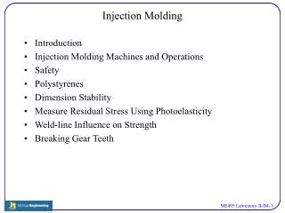
Introduction • Background • Concept is simple • Melt plastic, flow into mold and take part shape, cool, demold • Injection molding makes parts in discrete (discontinuous) process • More injection molding machines used for plastic processing than any other equipment • Almost all thermoplastic and some thermosets materials can be injection molded • Process is automated and highly repeatable parts • Injection molding parts are finished with little post molding operations • Very complex parts can be made • Machines are expensive • Molds are expensive, usually P-20 steel
Injection Molding Molds • The mold includes the shape of the part and is located between the stationary and movable platens of the injection molding machine • Key terms • sprue bushing- part of mold (cooled) • nozzle- end of injection (heated) • sprue channel- from bushing to runner • runners- feeds material from sprue to part • gate- mold area between runner and part • mold cavity- concave part of mold • mold core- convex part of mold • multi-cavity- more than one part in a cavity • ejectors- knock out pins • mold inserts- multiple cavities for same base • mold base- inserts used in same base • MUD base- Master Unit Die • draft angle- minimum angle from bottom to top of part • parting line- the split between core and cavity molds
Runner System • Several types of runners • single part runner • multiple part runner • symmetrical runner • non-symetrical runner • runner-less designs with hot manifolds
Runner System • Runner size considerations • Although properly sizing a runner to a given part and mold design has a tremendous pay-off, it is often overlooked since the basic principles are not widely understood. • Pros and cons of large runners • While large runners facilitate the flow of material at relatively low pressure requirements, they • require a longer cooling time, more material consumption and scrap, and more clamping force. • Pros and cons of small runners • Designing the smallest adequate runner system will maximize efficiency in both raw material use and energy consumption in molding. At the same time, however, runner size reduction is constrained by the molding machine's injection pressure capability.
Runner System • Runner Balancing is an essential for a balanced filling pattern with a reasonable pressure drop. • Payoffs of good runner design • A runner system that has been designed correctly will: • Achieve the optimal number of cavities • Deliver melt to the cavities • Balance filling of multiple cavities • Balance filling of multi-gate cavities • Minimize scrap • Eject easily • Maximize efficiency in energy consumption • Control the filling/packing/cycle time.
Hot Runner System • The ideal injection molding system delivers molded parts of uniform density, and free from all runners, flash, and gate stubs. • To achieve this, a hot runner system, in contrast to a cold runner system, is employed. The material in the hot runners is maintained in a molten state and is not ejected with the molded part. Hot runner systems are also referred to as hot-manifold systems, or runnerless molding. FIGURE 1. Hot runner system types: (a) the insulated hot runner, (b) the internally heated hot-runner system, and (c) the externally heated hot-runner system
Gate System • Several types of gates • rectangular simple gate • fan gate
Clamping Unit • Clamping Force • Clamping unit holds the molds together while the resin is injected, packed, and cooled, and ejected. • Clamping force is the rating of the injection molder, e.g., 150 tons clamping force. • Clamping force = Injection Pressure x Total Cavity Projected Area • Projected area is the area projected into a single plane, that is, the widest area of the part. • Examples • The force necessary to mold a part that has 100 in2 projected area and has 3,000 psi is 3,000 * 100 = 300,000 lbs force = 150 tons (note 1 ton = 2000 lbs) • The maximum projected surface area of a part on a 200 ton machine with a maximum injection pressure of 2,000 psi is: 400,000 lbs force / 2,000 psi = 200 in2
Ejector System • Several types of ejector systems • ejector plate • ejector pins • mechanical plate • hydraulic pins
Plastics Design for Injection Molding • Part Design • The underlying principles behind part design, other than part functionality are • cooling of plastic from melt to glassy state • heat transfer from various sections • thermal shrinkage of the plastic parts • Heat transfer is best when the parts have the same thickness. • Inside portions of parts cool more slowly than the part surfaces • Center portion will shrink more than the surface
Injection Molding Operations • Cycle Time ·Injection Pressure
Injection Pressure Equations • Equations • Based on a simplification of classic fluid mechanics theory • P is the injection pressure and n is a material constant (the power-law coefficient), which typically ranges from 0.15 to 0.36 (with 0.3 being a good approximation) for a variety of polymer melts. • Circular channel flow • The melt flow in the sprue, runner, and cylindrical gates • Strip channel flow • Such as melt flow in a thin cavity
Injection Molding Thermal Process • Temperature History in part
Injection Molding Operations • Fountain Effect Flow • Hot resin flow from the middle of the flow channel to the walls and cools
Injection Molding Process • Fill time • How long it takes to fill part. Faster filling rate = shorter fill time • Volume of part divided by volumetric flow rate • Note: Pressure is a function of the flow rate. Faster flow rate = higher pressures, except at very slow fill which causes larger core and smaller flow channel and then higher pressures.
Viscosity and Temperature and Shear Rate • Effects of temperature and pressure • Since the mobility of polymer molecular chains decreases with decreasing temperature, the flow resistance of polymer melt also greatly depends on the temperature. The melt viscosity decreases with increasing shear rate and temperature due to the disentanglement and alignment of the molecules and enhanced mobility of polymer molecules, respectively. In addition, the melt viscosity also depends on the pressure. The higher the pressure, the more viscous the melt becomes. • Shear rate: velocity divided by distance. • Higher shear rate = lower viscosity
Cavities • The number of cavities depends on the available production time, product quantity required, machine shot size and plasticizing capacities, shape and size of the moldings, and mold costs. • Number of cavities • Product Quantity: If the dimensional tolerance of the part is not very critical and a large number of moldings is required. • Machine shot capacity: Number of cavities = S / W
Sprue Guidelines • The sprue must not freeze before any other cross section. This is necessary to permit sufficient transmission of holding pressure. • The sprue must de-mold easily and reliably. Dco tmax + 1.5 mm Ds Dn + 1.0 mm 1º - 2º tan = Dco - Ds / 2L
Runner Guidelines • Common runners • Full-round runner • Trapezoidal runner • Modified trapezoidal runner (a combination of round and trapezoidal runner) • Half-round runner • Rectangular runner
Gate Design • Gate Design Overview • Single vs. multiple gates • Single gate is usually desirable because multiple gates have weld lines • Gate dimension • The gate thickness is usually two-thirds the part thickness. • The gate thickness controls packing time • Chose a larger gate if you're aiming for appearance, low residual stress, and better dimensional stability. • Gate location • Position the gate away from load-bearing areas. • Position the gate away from the thin section areas, or regions of sudden thickness change to avoid hesitation and sink marks
Gate Design • Gate Design Overview • Gate Types • Manually trimmed • Requires an operator to separate parts from runners during a secondary operation • Types include sprue, tab, edge, overlap, fan, disk, ring, film, diaphragm, spider • Automatically trimmed gates • Automatically trimmed gates incorporate features in the tool to break or shear the gate • Should be used to • Avoid gate removal as a secondary operation • Maintain consistent cycle times for all shots • Minimize gate scars • Types include Pin, Submarine, hot-runner, and valve
Gate Design • Design Rules • Gate location • Should be at the thickest area of the part, preferably at a spot where the function and appearance of the part are not impaired • Should be central so that flow lengths are equal to each extremity of the part • Gate symmetrically to avoid warpage • Vent properly to prevent air traps • Enlarge the gate to avoid jetting • Position weld and meld lines carefully • Gate Length • Gate length should be as short as possible to reduce an excessive pressure drop across the gate. Ranges from 1 to 1.5 mm (0.04 to 0.06 inches) • The gate thickness is normally 50 to 80 percent of the gated wall section thickness. Pin and submarine gates range from 0.25- 2.0 mm (0.01”- 0.08”) • The freeze-off time at the gate is the max effective cavity packing time. • Fiber-filled materials require larger gates to minimize breakage of the fibers
Boosting structural integrity with ribs • Structural integrity: the goal of every design • The major component of designing for structural integrity, in many cases, is to design the structure to be stiff enough to withstand expected loads. Increasing the thickness to achieve this is self-defeating, since it will: • Increase part weight and cost proportional to the increase in thickness. • Increase molding cycle time required to cool the larger mass of material. • Increase the probability of sink marks. • Well-designed ribs can overcome these disadvantages with only a marginal increase in part weight. • Typical uses for ribs • Covers, cabinets and body components with long, wide surfaces that must have good appearance with low weight. • Rollers and guides for paper handling, where the surface must be cylindrical. • Gear bodies, where the design calls for wide bearing surfaces on the center shaft and on the gear teeth. • Frames and supports.
Ribs Design • Design Rules • Keep part thickness as thin and uniform as possible. • This will shorten the cycle time, improve dimensional stability, and eliminate surface defects. . • If greater stiffness is required, reduce the spacing between ribs, which enables you to add more ribs. • Rib geometry • Rib thickness, height, and draft angle are related: excessive thickness will produce sinks on the opposite surface whereas small thickness and too great a draft will thin the rib tip too much for acceptable filling. • Ribs should be tapered (drafted) at one degree per side. • Less draft can be used, to one-half degree per side, if the steel that forms the sides of the rib is carefully polished. • The draft will increase the rib thickness from the tip to the root, by about 0.175 mm per centimeter of rib height, for each degree of draft angle. • The maximum recommended rib thickness, at the root, is 0.8 times the thickness of the base to which it is attached. • The typical root thickness ranges from 0.5 to 0.8 times the base thickness.
Recommended Design Parameters. • See Figure 1 for recommended design parameters.
Ribs Design Rules • Location of ribs, bosses, and gussets • Ribs aligned in the direction of the mold opening are the least expensive design option to tool. • As illustrated in Figure 1, a boss should not be placed next to a parallel wall; instead, offset the boss and use gussets to strengthen it. • Gussets can be used to support bosses that are away from the walls. The same design rules that apply for ribs also apply for gussets. • Alternative configurations • As shown in Below, ribs can take the shape of corrugations. • The advantage is that the wall thickness will be uniform and the draft angle can be placed on the opposite side of the mold, thereby avoiding the problem of the thinning rib tip. • Honeycomb ribbing attached to a flat surface provides excellent resistance to bending in all directions. • A hexagonal array of interconnected ribs will be more effective than a square array,with the same volume of material in the ribs.