Download
1 / 20
240 likes | 504 Views
Engineering Design Portfolio. Rick Rui Zhang. Professional statement ………………………....... 3 Overview ………..…………….………………… 4 Definition of Engineering Design ……………… 5 Personal Engineering Design Process …………. 6 Artifacts …………………………………………….. 10 Conceptual Design Report ..………………… 11

E N D
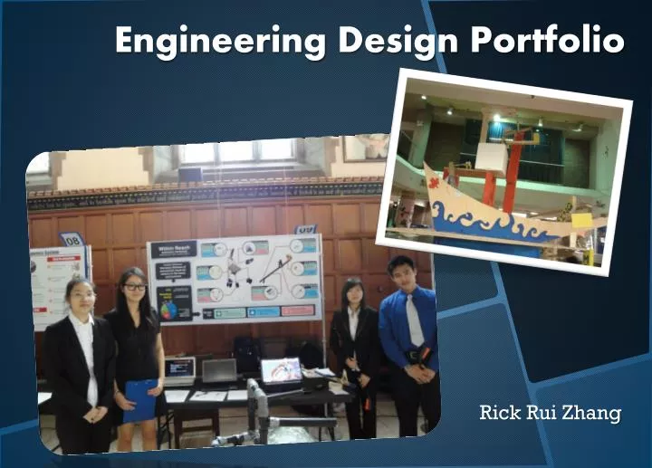
Engineering Design Portfolio Rick Rui Zhang
Professional statement ………………………....... 3 • Overview ………..…………….………………… 4 • Definition of Engineering Design ……………… 5 • Personal Engineering Design Process …………. 6 • Artifacts …………………………………………….. 10 • Conceptual Design Report ..………………… 11 • Detailed Design Report …………………………12 • Senior Reach RFP ………………………. 13 • CIV102 bridge ………………………… 15 • Rube Goldberg machine ………………………… 17 • Areas of Improvement ..………………………... 19 Contents
My name is Rick Rui Zhang, and I am a first year Engineering Science student at the University of Toronto. In the past 8 months, I have learned, defined and practiced engineering design in courses such as Praxis, CIV102 and beyond. These experiences has helped me to develop my personal perspectives and philosophies of the engineering design process, accompanied with some basic design/modeling skills. • I have participated in several design projects like conceptual and detailed design reports in Praxis I – where as a team solved problems that dealt with sleep deprivation during lectures and reusable writing mechanisms. Request of Proposal in Praxis II – where we tried to sustainably improve the quality of life of seniors in Toronto, by increasing the distance of convenient reach in the home environment. The bridge designs projects in CIV102, where truss and beam bridges were designed, followed by a series of calculations and then prototyped. Along with these courses related projects, I was also the construct/design executive of the U of T National Engineering Month club where a Rube Goldberg machine was designed, modeled and constructed from scratch. The design skills and the processes in which I have developed and practiced through these activities are reflected through the solutions I have proposed. • In this early stage as an engineering designer, my strength lies within my strong research skills as well as my ability to produce simple, effective, satisfactory designs, models and prototypes. And are demonstrated through the solutions to the Senior Reach RFP and CIV102 bridges. • An area I would like to improve on is my communication skills as I often find difficulty communicating ideas without the aid of drawing utensils. On top of that, I find it troublesome connecting and summarizing series of ideas together in the form of reports. Which were demonstrated in the conceptual and design reports, critique and, showcase. Limiting my development as an engineering designer. I intend to practice and participate in activities that will improve my presentation and writing skills in the future. Professional Statement
This portfolio looks at some of my design work completed through the 2011-2012 school year as an Engineering Science student at the University of Toronto. • The first part of this portfolio covers my personal design process, which were adopted and developed during my design experiences. • The second part consists of several design projects and activities which will identify my strength, areas of progress and areas for future development as an engineering designer. Overview
Engineering design is the process of which the optimal solution is created through the application of theories and practical science to meet specific needs, by evaluating the various aspects of safety, usability and sustainability. Personal Definition of Engineering Design
Improve/ • Redesign • Select • Setup Phase • Design Phase Personal Engineering Design Process • My Personal Engineering Design Process consists of two main phases: Setup and Design.
Original Design Process • It is worth noting that my current personal design process was not significantly modified from my original design process which were developed before university. The steps and the direction they are taken are relatively the same. However, my original steps did not include loops and the process did not consider focusing on the details of the solution such as meeting the metrics, criteria and constraints. • My current engineering design process was modified so that the solutions produced from the process is optimal. And that decision makings are based on solid researches and background information and thorough understanding of the problem. Solutions are presented in detailed sketches/models to present and communicate ideas.
Setup Phase • Identify Problem: The engineering design process begins with identifying the problem. This step is essential because it sets both the goals and objectives of the entire process. • My understanding of: goals are defined as the long term, general achievements. Where objectives are defined as the achievements that are more specific and are accomplished in a shorter period of time. • Understand: In order to proceed further with the problem, one has to fully understand the problem. Either trying to come up with a problem or trying to solve a problem. • This process is often accomplished by creating checklists and scope diagrams (much similar to the ones distributed in Praxis Studios), as it clearly outlines both the important and missing features. • Research: Based on the current understanding of the problem,I am set to gain further insights and background of the problem; by gathering information, defining stakeholders and community, finding possible reference designs and current solutions. Which will aid me in defining and understanding the problem further. Setting up possible, metrics, criteria and constraints; reframing the problem if necessary. • Brainstorm: Brainstorm enables me to solve the design problem through rapid and unrestricted exploration of ideas. One aspect of an idea often stimulates new ones. Working in groups enables each member to exploring more concepts which increases the chance of producing effective solutions. The sketches created during this process enables the communication between ideas quickly and effectively, and can later be used as the foundation to more detailed designs (ex. Solid-works). • Understand->Research->Brainstormforms a loop (as I call the setup phase). As my understanding of the problem enriches, my perspective may shift in different directions, and my approach might be set on a different path. As a result, I can define new need and set new objectives. • As Iloop over these processes again and again, Iwill eventually build strong foundations and understanding of the problem. And through frequent brainstorming, I will have come up with multiple designs or ideas. I will then filter the ideas, and select the idea that best fit the metrics, criteria and constrains I have setup through research for more detailed designing. • We now proceed to the design phase.
Design Phase • Mock-ups: Once an idea has been established and chosen. A mock-up of the solution often takes place first. • I define this step as the extra-low fidelity step. Where I will try to create a mock-up based on the selected design (sketch) from the set-up phase, using the whatever materials I have around me. • Analysis: Examine the problems that may occur based on the mock-ups and the design. Use various sample tests and pre-calculations to search for possible weaknesses and areas of improvement. The metrics, criteria and constrains may be adjusted, and detailed decisions such as dimensions, materials will be made using the info from research. • Engineering drawings or 3D modeling will be made based on the complexity of the design. • Prototyping: I will make the prototype according to the sketches (detailed drawings) and the detailed decisions. However, based on the complexity of the design and the amount of resources (which are often limited), low/medium/high prototypes will be made accordingly. • However, the prototypes may be optional as the resources and materials used are often limited. • Iteration/Testing: The designs are rarely perfect, and may often contain flaws. These flaws may happen in any of the previous steps: the prototyping process or from the initial designs. So in this process, I will have to again analyze the existing design, rework and fix the problem. • This design phase also formsa loop, because errors, doubts and new ideas may often be generated during the design phase, which means adjustments will have to be made. So the steps often has to be repeated. • However, when doubts and questions start to come up frequently, we often have to go back to more research and more idea generating (setup phase). • But if the solutions satisfy all the proposed metrics, criteria and constraints. The solution to the problem is produced.
Conceptual Design Report • Improving lecture Effectiveness • Detailed Design Report • Renewable writing utensils – UV erasable pen • Senior Reach • 3D Home Model • Walker • Reacher • CIV 102 • Truss Bridge Design • Beam Bridge Design • Ruth Gold Berg Machine • Design + 3D Model • Construction Artifacts I would like to note that used to illustrate my engineering design process are mainly group projects. However, I will identify my contribution to the artifact along with its relevance with the design process.
The setup phase is demonstrated by the Conceptual Design Assignment from Praxis I. My team was given the “Increasing Lecture Effectiveness” brief which was to improve the student’s learning experience by preventing them from falling asleep during lectures. It was a good topic, because I experienced such problems myself, and developing such bad habits really affects one’s understanding of the lecture contents. I contributed to the assignment by researching topics such as all the possible causes of sleep deprivation, specifically in class; for different age groups, gender and race. The current existing methods preventing sleep or stress and the architectural designs of lecture rooms in U of T and how the layout of the room improve lecture, etc. From there, my team combined all our researches, followed by discussions on the current solutions/reference designs. Through series of diagrams, Pugh charts, rough sketches (ex. Layout of lecture rooms) and more research. My team decided that developing better time management skills, reducing stress and improving hearing abilities are some of the possible and realistic solutions to improving lecture effectiveness. In addition, we reframed and adjusted some of the criteria and constraints. Thus, the setup phase was followed in the conceptual design report. Conceptual Design Report The infrared massage patch was designed to help users reducing stress and the wristband is a activity monitoring device that improves the user’s time management skills.
The Detailed Design Report in Praxis I demonstrates my development and progress in the design phase. • The report focused on finding solutions to renewable writing utensils. The conceptual design report given to us already had 3 solutions, and we chose the solution that was the most favourable - UV erasable pen, without knowing whether the solution legitimate or solidly researched. So minimal research and detailed decision making were made and my team went straight to prototyping, avoiding some of the obvious flaws such as safety issues related to UV lights and the overheating of the UV power source built into the pen. And so, my team was penalized in the evaluation. Detailed Design Report • From there, I always made sure that research and analysis were implanted in the design process. This modification to my design process is later shown in my solutions to Senior Reach RFP in Praxis II.
My personal engineering design process (both setup and design phase) is illustrated through solving the Senior Reach RFP this semester. The senior reach RFP addresses the need to “Improving the reaching ability in seniors using ambulatory aids in order to prevent injury and ensure quality of life”. After a series of research on falling related injuries, design sketches and team discussions, we decided to integrate both already existing reachersand walkers to prevent senior related (ex. falling) injuries while reaching for objects in a home environment. Senior Reach RFP • We also reframed the community in need as “seniors that have enough strength to pick up a pickle jar and are able to stand up straight and walk (within the home) without nurturing assistances”. • On the left is a 3D model of a house I made to demonstrates the use of the reacher and walker by seniors in the home environment such as the: kitchen, living room, bedroom and washroom.
The above photos of the low and high fidelity walker I made using ABS pipes as the frame, wood, sponges and duck for the seat, cardboard for the wheels. • We further refined the solutions by making detailed decisions. For example, the walker consists of 5 wheels to increase stability, triangular and aluminum framed structure for better maneuverability, balance bar and folded chair to increase support. As for the reacher, arm support and easier grip to reduced strain on the wrist and forearm. Carbon fibre frame for reduce self-weight and silicon to prevent the object from slipping off the reacher. I was in charge of researching for the walker, designing both the walker and reacher (I did the rough sketch, another group member made the 3D model), purchasing the necessary materials and producing both prototypes. However, I spent most time constructing the walker by myself (both low and medium fidelity), testing for possible failure every step of the way; while the rest of the team helped me construct the reacher. Thus, the design process was met from understanding the problem, researching for solutions, idea generating through sketches and 3D modeling. Analyzing, prototyping and testing. Senior Reach RFP (cont.)
The design process (both setup and design phase) is demonstrated from the CIV102 Bridge Designing Projects in the fall term. Designing truss bridge on St.George street connecting Bahen Centre and Galbraith building (calculation and engineering drawing only), and Mat board beam bridge design (functional prototype + report). Because the problem for both bridge projects given were well defined, with the required knowledge taught in lectures and tutorials, minimal research were required. However, my group members and I made dozens of bridge sketches with special themes (as the best theme will be given 0.5-1% bonus). Various types of calculations (ex. Shear, wind bracing) were made and later putted into spread sheet. However, the only testing and prototyping possible for the St.George bridge design was calculations and appropriate designs. • When choosing the final design of the bridge, the one that was most favourable was chosen with no comparison and filtering with the given criteria and constraints. Flaws were found later which complicated the design (ex. Stress calculations). CIV102Bridge • On the left, is a engineering drawing I produced for the St.George bridge report. Both side of the small truss spells ENG (stands for ENGINEERING).
As for the beam bridge design, minimal research was required. But sketches were made and compared to similar existing bridges. Various calculations were made and tested with different scenarios using a program called “beam-boy”. Low fidelity prototype was made using the provided Mat-board and tested throughout the process, series of mini tests was consulted after its completion. However, the prototyping step was troublesome and problematic, as it was difficult to cut the T shaped diaphrams without damaging the sides. Bridge Design (cont.)
I took the role as the Construction/design executive for National Engineering Month this school year (2011-2012). Me and dozen other engineering students built a Rube Goldberg Machine in the Standford Fleming Atrium. This activity also demonstrates my designing process – although it was not done as professionally as the previous artifacts, the designing processes still applies. • The problem (goal) was to create a Rube Gold Berg Machine, the research was done by studying the existing machines on YouTube. Couples dozens of sketches were made, analyzed, critiqued and sometimes integrated by others (setup phase). Six Designs were chosen, and rough 3D modeling were made through Google sketch-up, solid-works and Open-Scad. However, most of the 3D designing were produced by upper year engineering students. Followed by designing, I was in charge of buying materials (ex. Metal balls, springs, motor, strings etc.) at a store called Active Surplus. Small samples and rough sketches were made before every construction session, and work were divided into pairs, to working on different parts of the machine. As the executive, I was involved in building each part of the machine and assembling them all together. Series of trials, tests and adjustment (minor and major) were made throughout (design phase). Rube Goldberg Machine
Rube Goldberg Machine (cont.) • Here is a link to this year’s Rube Goldberg machine video: • http://www.youtube.com/watch?v=QD3HCkhSROg
My strengths in the engineering design process are strong research skills, designing+ prototyping. The former applies to the setup phase, while the latter applies to both phases of my design process. As described through my artifacts, I am able to research for valuable and relevant information, articles and studies in detail. Even though hard to prove, most of the detailed decisions were made based on my solid research. On the other hand, I am very creative and productive with engineering drawings, sketches and prototypes. I am always able to complete these tasks with my groups members satisfied and confident. Taking the 3D home model from the Senior Reach RFP for instance, I was able to demonstrate every aspect on how and where the walker and reacher individually and as a combination in the home environment; by creating a 3 min animation displaying the various details and perspectives. Areas of Improvement The photos shows the folding seat I made using thin wood, sponges and camouflage duck tape. 9 out of 10 people actually thought I took it off another walker/chair.
Areas of Improvement (cont.) Even though I was able to follow through my engineering design process, I still need to further develop my engineering communication skills such as trying to delivering my ideas and thoughts through speaking, rather than sketches and rough drawings. For example, in Praxis I and II, I found it difficult to communicate the exact idea and thoughts I have with the Teaching Team during Critiques and Team Liaison– support from group members were often needed to help me complete my point and argument during the Q&A periods. As for the writing components, even though I had solid research and background information, I had difficulty and was lacking the ability to tie everything together – in the form of paragraphs and reports. My group members often assisted me in these areas. And as for the Showcase, even though series of practices were taken place before the showcase, I still found it difficult to communicate my ideas as I may have lacked the confidence, engineering arguments techniques and terms. Therefore, I should on improving my engineering communication skills – writing and speaking, as they will be crucial in my future development as an engineering designer.