Download
1 / 28
280 likes | 408 Views
Data Transmissions Laboratory, Technical University of Cluj-Napoca. Zsolt Polgar, Vasile Bota, Mihaly Varga. Performances of LDPC-Error Detecting Concatenated Codes Used in Adaptive OFDM Transmissions. Overview. LDPC-error detecting code concatenation

E N D
Data Transmissions Laboratory, Technical University of Cluj-Napoca Zsolt Polgar, Vasile Bota, Mihaly Varga Performances of LDPC-Error Detecting Concatenated Codes Used in Adaptive OFDM Transmissions
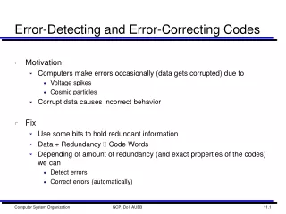
Overview • LDPC-error detecting code concatenation • Message passing decoding of LDPC codes when correct bits can be identified • LDPC and error detecting concatenated codes applied in adaptive OFDM downlink transmissions • BCH error detecting codes adapted to the considered OFDM transmission scheme • Questions for further study
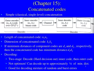
LDPC code concatenated with error detecting codes • consider an n’-bit long LDPC code, n’ high (several hundred at least) concatenated with m error detecting codes (ED), of different lengths, as shown in figure 1 – filled segments represent the ED codes control bits. • the information bits are first LDPC coded (external code); • the obtained codeword, n’-bit long, is divided into m equal or non-equal groups, G1 to Gm; • each group is coded with a high rate ED code; • the final code word is obtained by concatenating the m code words generated by codes G1 to Gm; Fig.1 Concatenation of an LDPC code with m shorter error detecting codes
Message passing decoding of LDPC codes when correct bits can be identified • using the concatenation method described previously in fig. 1, the LDPC coded bits located in each of the m distinct groups can be identified as correct or incorrect bits • Questions: if the LDPC coded bits located in some groups are identified as correct bits, how could this information be usedby the LDPC-message passing decoding and what is the impact of this information upon the LDPC code performances ? Brief analysis of the message-passing decoding algorithm for regular binary LDPC codes • the message passing decoding is based on the Tanner graph associated to the LDPC code; the graph is composed of bit nodes (the bits of the codeword) and check nodes (the check equations associated to the code) – see fig. 2 • for a regular LDPC code, each bit node (or variable node) is connected to dv check nodes (the order of the bit node) and each check node is connected to dc bit nodes (the order of the check node) • the coding rate of such a regular LDPC code is: (1)
Message passing decoding of LDPC codes when correct bits can be identified • the decoding process tries to adjust the a posteriori probabilities p0 and p1 of each bit node, based on the messages exchanged between the bit and control nodes • if mk = log (pk0/pk1), k=1,…,dv are the log-likelihood ratios of conditional a posteriori probabilities of a given bit value, conditioned by independent random variables (the value of the check nodes in this case), the message generated by a bit node (variable node) is: (2) m0 being the initial log-likelihood ratio • a check node receives dc log likelihood ratios, log (pk0/pk1), from the bit nodes connected to it and computes the conditional probabilities p’0t – the bit with index t equals “0” and p’1t – the bit with index t equals “1”; these probabilities are conditioned by the fulfilling of the considered check equation and by the probabilities of the other bit nodes connected to this equation: (3) • finally, the log-likelihood ratio, log (p’0t/p’1t), is computed and transmitted to bit- node t
Message passing decoding of LDPC codes when correct bits can be identified Fig.2 Tanner graph associated to (dv=3 ; dc=6) regular LDPC • let’s consider that a number of code bits can be identified as correct bits and these bits are uniformly distributed in each group of dc bits connected to a check node; then, in each group of dc bits connected to a check equation, dn bits can be correctly decided (without LDPC decoding). • since these bits are correctly decided, the a posteriori probabilities assigned to them will be constant: pk0=1, pk1=0 or pk0=0, pk1=1 the messages generated by these bits are constant. • the equation (3) assigned to the control nodes becomes : (4)
Message passing decoding of LDPC codes when correct bits can be identified • equation (4) shows that, if in each group of dc bits the same number of correct bits can be identified and if these bits generate appropriate constant messages, the check-node order decreases and, consequently, a virtual decrease of the coding rate occurs, see eq. (1), while the actual coding rate remains the same. • Question: if group of consecutive LDPC bits are controlled by an ED code, what are the types of LDPC codes for which the correctly decided bits are uniformly distributed in groups of dc bits? How could these codes be generated ? • Structural properties of L(m,q) regular LDPC codes [5] [6] • L(m,q) codes have a codeword length of N = qm, where q is a prime number or a power of a prime number and m is a natural number. • the control matrix H of such a code is generated by removing a number of rows, according to the desired coding rate, out of a square matrix M (qm qm). • each row of matrix M is composed of q square sub-matrices of (qm-1 qm-1) elements each; these sub-matrices are obtained by permutations from a basis sub-matrix. • the above mentioned properties show that each control equation has a single connection with a group of qm-1 code bits and that each control equation is connected to each group of qm-1 code bits.
Message passing decoding of LDPC codes when correct bits can be identified • fig. 3 presents the M matrix associated to an L(2,5) regular LDPC code, and the H matrix associated to a 0.4-rate code obtained from the M matrix by retaining k = 5 columns and j=3 lines of basic sub-matrices. • the mentioned properties of this type of codes show that, if groups of Kqm-1 LDPC bits are controlled by error detecting codes, then the number of correctly decided bits connected to each control node will be the same, equaling K. Note: if the lengths of the error detecting codes are not Kqm-1, some kind of non-regular LDPC codes are obtained Fig.3 The M matrix associated to an L(2,5) regular LDPC code and the H matrix associated to a k=5, j=3, p=5 L(2,5) type, 0.4-rate LDPC code
Message passing decoding of LDPC codes when correct bits can be identified • Decoding the concatenated LDPC-ED codes. Simulation results • the initial a posteriori probabilities of each bit are computed using the received levels and the noise distribution; these probabilities are stored; • the received bits are decided, employing these probabilities (Bayes criterion) and the ED code words are decoded the correct bits are identified and the ED check bits are discarded; • the LDPC code is decoded using the initial a posteriori probabilities, for the bits that were not included in correctly received ED code words, and the information related to the correct bits, indicated by the ED code; • The bloc diagram of such a decoder is presented in fig. 4 • some simulation results obtained for tree L(2,q) codes with different code lengths and different number of identified correct bits are presented in fig. 5 – fig. 7. • tables 1 – 3 show the main parameters of the codes employed.
Message passing decoding of LDPC codes when correct bits can be identified
2 3 1 4 5 6 Message passing decoding of LDPC codes when correct bits can be identified. Simulation results Fig.5 Performances of a L(2,29) LDPC codes with k=28, j=3, p=29 parameters decoded considering different numbers of correct bits indicated by the ED code
2 3 1 4 5 6 Message passing decoding of LDPC codes when correct bits can be identified. Simulation results Fig. 6 Performances of a L(2,31) LDPC codes with k=27, j=3, p=31 parameters decoded considering different numbers of correct bits indicated by the ED code
2 3 1 4 5 6 Message passing decoding of LDPC codes when correct bits can be identified. Simulation results Fig. 7 Performances of a L(2,71) LDPC codes with k=71, j=3, p=71 parameters decoded considering different numbers of correct bits indicated by the ED code
LDPC and error detecting concatenated codes applied in adaptive OFDM downlink transmissions • the proposed code concatenation was experimented in the downlink scheme proposed in the WINNER project. • this scheme uses a special data structure, which is adapted to the frequency selectivity (due to the multipath propagation) and fast fading (due to the motion of the user) characteristic to a radio channel; • this structure is called chunk and it is composed of 8 OFDM subcarriers and 12 OFDM symbols – OFDM sub-carrier separation = 39,062Hz ; OFDM symbol period (with guard interval) = 28.8s; only 81 QAM-symbols are payload symbols, out of the 96 included in a chunk; • adaptive QAM modulation is used in each chunk according to the predicted SNR; adaptive coded modulation could also be used in each chunk • the LDPC codes are used to code the bit sequence designated to a certain user; the encoded sequence is loaded onto several chunks; for each possible chunk load (depending on the number of bits/symbol of the selected QAM modulation), a different ED code is used; • this code has as information bits the bits generated by the LDPC coding; • the length of this ED code should match the number of bits loaded in the chunk; if adaptive QAM modulations are used with i bits/symbol, i=1,…k, k separate ED codes would be used;
LDPC and error detecting concatenated codes applied in adaptive OFDM downlink transmissions • Simulation conditions • adaptive non-coded modulation in each chunk with i bits/symbol i=1,…8; the SNR thresholds associated to the modulations used are presented in table 4; • Nus = 1 user/site; • ED codes were not used in these simulations; the error detection was done by comparing the received and transmitted bits; • WP5 macro urban model was employed for the channel simulation; • the background SNR ranges between 1dB and 19dB, with a 3dB step; • for each background SNR a different high-rate L(2,q)-type LDPC code was used, with different length that match closely the average length of a 8-chunk data packet - to simplify the results interpretation. – the codes used for each background SNR are presented in table 6. • the 8-chunk long data packet is proposed in the WINNER project as a possible MAC access packet. • the simulations were also performed, for each background SNR, with different constant rate LDPC codes, with a non-modified MP decoding; the length of the code is constant for a given background SNR and is related to the average number of bits/ QAM symbol – see table 5 for these parameter and other parameters related to the non-coded transmission • the proposed modified LDPC decoding method is equivalent to a virtual decrease of the coding rate according to the number of correct bits detected. • it is of interest to compare the performances ensured by the proposed modified LDPC decoding, with the performances obtained by using constant rate codes, decoded with classical MP decoding. • the constant rate of these codes is selected to mach in average the virtual rate of the LDPC code decoded with correct bits, i.e. modified MP decoding.
LDPC and error detecting concatenated codes applied in adaptive OFDM downlink transmissions
LDPC - and error detecting concatenated codes applied in adaptive OFDM downlink transmissions
LDPC and error detecting concatenated codes applied in adaptive OFDM downlink transmissions • three parameters were measured for each background SNR and each code employed – 9 cases were considered: • a high rate code (0.94 ) decoded considering the correct bits. • 8 codes normally decoded with the same length and different coding rates, matching in average the virtual coding rates of the LDPC code decoded considering the correct bits – see table 6. • NOTE: the use of different code lengths for different background SNR has a negligible effect on overall performances because the coding gain remains relative constant with the code length if this length is relatively large – see fig.8. • the measured parameters are: bit error, 8-chunk packet error rate, spectral efficiency • the analysis of the results requires the evaluation of the probability to have a given number of correct chunks in an 8-chunk packet received – this parameter is related to the number of correctly received bits. • the average performance of the proposed decoding method depends on the average number of correct bits detected in a LDPC-codeword, parameter directly related to the probability to have a given number of correct chunks within a packet – see figure 9 which shows these probabilities.
2 3 1 4 LDPC and error detecting concatenated codes applied in adaptive OFDM downlink transmissions Fig.8 Performances of the L(2,p) LDPC codes with different lengths and approximately the same rate • the LDPC codes considered in figure 8, with approximately the same rate and different lengths, have the coding gain located in a range of 0.5dB; the SNR variation step used in simulations also equaled 0.5dB .
LDPC and error detecting concatenated codes applied in adaptive OFDM downlink transmissions Fig.9 The probabilities to have x correct chunk in a 8-chunk packet vs. the background SNR; x= 0, 2, 3, 4, 5, 6, 7, 8 • the occurrence of 6, 7 and 8 correct chunks within an 8-chunk packet are the most probable – these cases establish practically the spectral efficiency of the transmission in which an ARQ protocol is used to manage the 8-chunk packets
LDPC and error detecting concatenated codes applied in adaptive OFDM downlink transmissions • the bit error rates, 8-chunk packet error rates and the spectral efficiencies of the transmissions using the proposed coding method and the LDPC coding, with different rates and classical decoding, are presented in figures 10 - 12. Fig. 11 8-chunk packet error rates of the tested coding methods Fig. 10 Bit error rates of the tested coding methods
LDPC and error detecting concatenated codes applied in adaptive OFDM downlink transmissions Fig.12 Spectral efficiencies of the tested coding methods • Conclusions • the proposed coding-decoding method ensures a low average bit error and packet error probabilities; both probabilities are located between the values ensured by normally decoded codes with Rc=0.5 and Rc=0.75; • the spectral efficiency is also high; it is approximately equal with the value ensured by a high rate (0.94) LDPC code with large codeword length;
LDPC and error detecting concatenated codes applied in adaptive OFDM downlink transmissions • comparison between the performances of the proposed coding method and adaptive coded modulation used at the chunk level, which is an alternative option, worth to be analyzed. • the adaptive coded modulations used are shown in table 8 and some parameters characterizing the transmission scheme are presented in table 9; • figures 13 – 15 show comparatively the bit error rate, 8-chunk packet-error rate and spectral efficiency of the proposed coding method, at the packet-level, and of the chunk-level coding.
LDPC and error detecting concatenated codes applied in adaptive OFDM downlink transmissions • the proposed packet coding method ensures lower average bit and packet error rates, than the adaptive chunk-coded configurations and packet-coded configurations which use high-rate LDPC codes and classical MP decoding. Fig.14 8-chunk packet-error rates of non-coded, chunk-coded and packet-coded configurations Fig.13 Bit error rates of tested non-coded, chunk- coded and packet-coded configurations
LDPC and error detecting concatenated codes applied in adaptive OFDM downlink transmissions • Conclusions • the adaptive chunk-coded modulation ensures the highest spectral eficiency, but the proposed packet-coding method provides a close spectral efficiency. • the main advantage of the proposed packet-coding is the fact that high spectral eficiency is ensured together with low bit-error probability; the method can fulfill the requirements imposed by different type of services. Fig.15 Spectral efficiencies of the tested non-coded, chunk- coded and packet-coded configurations
BCH error detecting codes adapted to the considered OFDM transmission scheme • high rates error detecting codes with low undetected error probability are required; the undetected error probability can be approximated as: (5) where n is the codeword length and k is number of information bits; p=n-k. • taking into account the chunk structure of the considered transmission system (81 data symbols/chunk) and the type of used adaptive modulations (QAM with i bits/symbol, i=1…8), the BCH codes specified in table 10 could be used as ED codes in the proposed coding technique based on concatenated codes. • considering the probabilities the packet error rate and the spectral efficiency requirements, the possible solutions are those corresponding to Code 2 of table 10.
Questions for further study • Elaboration of detection algorithms of correct LDPC bits that use the LDPC check equations [2]; the ED codes are not required this way, avoiding the coding rate decrease due to these codes; • Concatenation of a long LDPC code (at packet-level) with m shorter LDPC codes (at chunk-level) used both for error correction and error detection • for LDPC codes decoded with the MP algorithm, the probability to obtain after decoding a valid codeword, different to the original codeword, is relatively low (even very low ); if the MP decoding fails, it would not generate a valid codeword (with very high probability) the internal LDPC codes can do combined error correction and error detection. The correct(ed) bits identified this way, could be used to improve the decoding performances of the external LDPC code.
References (selected) [1] J. Hagenauer, “The Turbo principle in Communications”, Proc. of Nordic Radio Symposium, August 2004, Oulu, Finland. [2] M. G. Luby, M. Mitzenmacher, “Verification Base Decoding for Packet-Based LDPC Codes”, IEEE Trans. Inform. Theory, vol. 51, No.1, Jan. 2005. [3] ETSI, “ETSI EN 302 307 v1.1.1”, DVB-S2 standard, 2004. [4] T. Richardson, R. Urbanke, “Capacity of Low Density Parity Check Codes Under Message Passing Decoding”, IEEE Trans. Inform. Theory, vol. 47, Feb. 2001. [5] J.L.Kim, U.N. Peled, I. Prepelitsa, V. Pless, S. Friedland, “Explicit Construction of Families of LDPC Codes of girth at least six”, Proc. of 40th Allerton Conference on Communication, Oct. 22, 2002. [6] E. Eleftheriou, S. Olcer, “G.gen:G.dmt.bis:G.lite.bis: Efficient Encoding of LDPC Codes for ADSL”, ITU-T, Doc. SC-064, 2002. [7] IST-2003-507581 WINNER, “Final report on identified RI key technologies”, Report D2.10 v1.0,23 Dec. 2005. [8] M. Sternad, T. Ottosson, A. Ahlen, A. Svensson, “Attaining both Coverage and High Spectral Efficiency with Adaptive OFDM Downlinks”, Proc. of VTC 2003, 2003, Orlando, Florida. [9] G. Wade, Signal Coding and Processing, Cambridge University Press, 1994.