Download
1 / 30
300 likes | 406 Views
Learn about standard formulas and interaction models for specifying interactive systems, including formal notations for communication and analysis, model-oriented notations, algebraic notations, and temporal logics. Explore the PIE model, predictability, observability principles, specific domain models, and continuous behaviors in engineering and virtual worlds. Gain insights into status-event analysis and the concept of hybrid models in system modeling.

E N D
Models of the System By Eric Douangmala, Matthew King, Justin Pardue, and Erica Kaufman
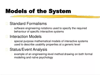
Introduction • Standard formulas are to be used to specify interactive systems. • Interaction models describe general properties of systems • There are ways to model phenomena that involve continuous interactions; like dragging an icon and time issues
Standard Formulas • Formal notations for communication • Formal notations for analysis • Model-orientated notations • Issues for model-orientated notations • Algebraic notations • Temporal and other logics
Formal notations for communication • Common language created by design team and system developers • Language must be understood by both groups • Documentation is needed • Language must also be interpreted to outsiders
Formal notations for analysis • Formal specifications can be analyzed in many different ways • The task of verification benefits a formal specification • Specifications can be checked for external consistency with respect to requirements
Model-oriented notations • Developed in 1970s and 1980s to provide software engineers to describe and reason using mathematical concepts, like programming languages • Two major model notations used today are Z and VDM. • Z has been used to specify editors, window managing, and graphics toolkit
Issues for model-oriented notations • Interface issues • Framing problem: everything else stays the same and can be complicated with state invariants • Internal and External consistencies • Separation issue: whether or not distinction of system functionality and presentation is explicit
Algebraic Notations • Various number of specification notations • Examples: OBJ, Larch, ACT-ONE • Algebraic notations describes what the object form from the outside, the behavior of a system from a user’s viewpoint instead of internal structure.
Temporal and other logics • Familiarity with standard propositional logic, letters used to represent logical statements • Temporal logic: operators to reason about time • Real time: temporal logic is about the succession of events, one thing happening before another, not actual seconds, minutes, or hours.
Interaction Models • This section describes how systems should be ‘what you see it was you get’, consistent, and contain a universal undo facility. For simple jobs WYSIWYG is sufficient, but for more complex jobs what does WYSIWYG really mean? • This section will define generic interaction models.
The PIE Model • The PIEmodel is a black-box model, it describes the system purely in terms of its inputs from the user and outputs to the user. • The difference between the ephemeral display of a system and the permanent result is central to the PIE model. • When applying the PIE model at different levels it is possible to map between the levels.
Predictability and Observability • WYSIWYG can have two interpretations: what you see is what you will get and what you see is what you have in the system. These are observability principles. • If there are two graphical icons stacked on each other and the pointer gives you no notification as to which one you will choose this is predictability.
Specific Domain Models • Windowed Systems – Describes the interference properties between windows. • Timing – When the user’s actions get ahead of the computers ability to process the input. • Attention – Describes which parts of the display and result are used during any particular task. • Non-Determinism – If you are ignorant of certain information in a system, it may appear to behave non-deterministically. • Dynamic Pointers – Interface objects often have special positions, such as the cursor or marked blocks.
Dealing With The Mouse • The PIE model is very asymmetric between input and output. • A mouse click is similar to a keystroke: each is as event. • The mouse’s position is similar to the screen: they both have an observable value at any moment – we say each of those is a status.
Status – Event Analysis • Status – event analysis distinguishes events that occur at specific moments of time from status phenomena that have values over a period of time. • Examples include keyboard strokes and mouse click beeps. • Status – event analysis is really a conceptual framework for viewing interaction, but does have several concrete models, both descriptive models and specification notations.
Making Everything Continuous • In engineering and physics, the idea of modeling continuous behavior being a special problem would seem strange. • In those fields, and in real life, continuous phenomena are normal – discrete things are the exception. • Objects in virtual worlds have to have similar behavior, and Wuthrich [384] has used general versions of this kind of equation from cybernetic systems theory to model virtual reality systems.
Hybrid Models • Hybrid Systems arise when control systems interact with real physical systems such as industrial controllers or fly-by-wire aircraft. • This hybrid community has a largely dualist model of the world, with discrete computer systems interfacing with a continuous environment defined by differential equations. • The TACIT project studied a variety of continuous-time interactive systems and also considered modeling using hybrid high-level Petri nets. • Petri nets allow us to express concurrent behavior, but have discrete behavior with tokens moving between places at transitions.
Precise Time Intervals • Precision in modeling is important to ensure that when we describe things we do not accidentally leave out the moment of time between two intervals, or accidentally have intervals overlap by one moment when we mean them to be disjoint.
Exercise descriptions • A. Model based and partial description completion • B. Partial descriptions for state changes • C. Actual descriptions for actions • D. Statement testing
Part A Target_For_Override: { Pressure, Temp, Flow } Shutdown_State: {Normal, Waiting_Confirm, Confirmed} The above answer is for clarity and not specific on special values for this scenario
Part B2 Answer: • Confirm: if (Shutdown_State is Waiting_Confirm ) then set Shutdown _State to Confirmed • Cancel: if (Shutdown_State is Waiting_Confirm ) then set Shutdown _State to Normal
Part C Answer alarm_higher [plus key is pressed] if ( Alarm_State is Red or Alarm State is TempRed ) then do nothing if ( Alarm_State is Amber ) then set Alarm_State to TempRed and set Confirm_Needed to true if (Alarm_State is Green) then set Alarm_State to Amber shutdown [IMMEDIATE SHUTDOWN COMMENCE button pressed] if (Shutdown_State is Normal ) then set Shutdown_State to Waiting_Confirm and set Confirm_Needed to true otherwise do nothing select_target(targ) [the target pulldown has been used] set Target_For_Override to targ set Manual_Override_Value to zero set_target_value [the SET button has been pressed] if ( Alarm_State is not Red ) then do nothing otherwise ... if (Target_For_Override is Pressure ) then set Target_Pressure to Manual_Override_Value if (Target_For_Override is Temp ) then set Target_Temp to Manual_Override_Value if (Target_For_Override is Flow ) then set Target_Flow to Manual_Override_Value
Initial state: Alarm_State is Green Confirm_Needed is false etc. … Steps 1, 2 – no system actions Step 3 – press '+' twice alarm_higher: Alarm_State = Amber alarm_higher: Alarm_State = TempRed Confirm_Needed = True Step 4 – button glows because Confirm_Needed = True Step 5 – no system action Step 6 – select pressure select_target(Pressure): Target_For_Override = Pressure Manual_Override_Value = 0 Step 7 – types the new value '6000' Keypad_digit(6): Manual_Override_Value = 6 Keypad_digit(0): Manual_Override_Value = 60 Keypad_digit(0), Keypad_digit(0): Manual_Override_Value = 6000 Step 8, 9 – no system action Step 10 – presses the SET button set_target_value: nothing happens (Alarm_State not Red) Step 11 – no system action Step 12 – system action outside control panel being modelled Step 13,14 – as with step 10,11 nothing changes Step 15, 16, 17 – as steps 6, 7, 10, 11 and 12 Step 18 – no system action Step 19 – as step 12 Step 20 – presses "Immediate Emergency Commence" shutdown: Shutdown_State = Waiting_Confirm Confirm_Needed = true Step 21 – button glows because Confirm_Needed = True Step 22 – no system action Step 20 – presses "Immediate Emergency Commence" confirm: Shutdown_State = Confirmed Confirm_Needed = false Step 24, 25 – action outside description of control panel