Download

1 / 20
200 likes | 201 Views
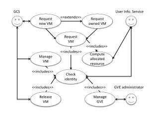
Setup for VM launch. Using ‘vmxwrite’ and ‘vmxread’ for access to state-information in a Virtual Machine Control Structure. VM and VMM. A virtual machine, and its Virtual Machine Manager, each need a supporting VMCS. Guest VMCS (4K-aligned). VM. VM exit. Host VMCS (4K-aligned). VM entry.

E N D
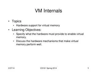
Setup for VM launch Using ‘vmxwrite’ and ‘vmxread’ for access to state-information in a Virtual Machine Control Structure
VM and VMM • A virtual machine, and its Virtual Machine Manager, each need a supporting VMCS Guest VMCS (4K-aligned) VM VM exit Host VMCS (4K-aligned) VM entry VMM VMXon VMXoff
Access to VMCS • Software must initialize the first longword with the CPU’s VMX revision-identifier in advance of any use by VMX instructions • Get ‘revision-identifier’ from MSR (0x480) • Any further access to the VMCS is indirect (because layout varies among processors) • The ‘vmwrite’ and ‘vmread’ instructions are used to access the VMCS fields indirectly
Over one hundred fields! • Each field within the VMCS is specified by its unique 32-bit field-encoding 31 15 14 13 12 11 10 9 1 0 reserved (=0) W 0 T INDEX A Legend: W (width of field): 00=16-bit, 01=64-bit, 10=32-bit, 11=natural-width T (Type of field): 00=control, 01=read-only, 10=guest-state, 11=host-state A (Access-type): 0= full, 1=high (NOTE: Access-type must be ‘full’ for 16-bit, 32-bit, and ‘natural’ widths)
‘vmwrite’ • Source operand is in register or memory • Destination operand is the ‘field-encoding’ for a VMCS component and is in a register # Example: the CR3 target-count control has field-encoding 0x0000400A # Here we setup that VMCS-component’s value so it will be equal to 2 .code64 mov $0x0000400A, %rax # field-encoding into RAX mov $2, %rbx # component-value in RBX vmwrite %rbx, %rax # write value to VMCS field
‘vmread’ • Source operand is the ‘field encoding’ for a VMCS component and is in a register; the destination operand is register or memory # Example: the Exit Reason component has field-encoding 0x00004402 # Here we read that VMCS-component’s 32-bit value into a memory-variable .code64 mov $0x00004402, %rax # field-encoding into RAX lea Exit_Reason, %rbx # memory-address into RBX vmread %rax, (%rbx) # read value from VMCS field #------------------------------------------------------------------------------------------------------ Exit_Reason: .space 4 # storage for the Exit Reason
Our ‘machine’ array • In our ‘vmxstep3.s’ source-file we create a complete set of memory-variables for all the VMCS components, together with an array of (field-encoding, variable-address) pairs; our array is named ‘machine[]’ • This allows us to create a program-loop which initializes all the VMCS components in a uniform way, despite varying widths
Categories of variables • The components of the VMCS fall into six categories: • Guest-state components • Host-state components • VM-execution Control fieldss • VM-entry Control fields • VM-exit Control fields • VM-exit Information fields
Main Guest-State fields • Program memory-segment registers • ES, CS, SS, DS, FS, GS • System memory-segment registers • LDTR, TR, GDTR, IDTR • Processor Control Registers • CR0, CR3, CR4, DR7 • Processor General Registers • RSP, RIP, RFLAGS
For a Virtual-8086 guest-task • All program memory-segment registers have 64K segment-limits (0xFFFF) with their ‘access-rights’ equal to 0x00F3 (i.e., present, readable, writable, executable, and requested privilege-level equal to 3) • Segment base-addresses must be equal to segment-selectors times sixteen (for real-mode style memory-addressing)
Guest System Segments • The base-address and segment-limit for LDTR, TR, GDTR, and IDTR registers can be setup using the symbolic addresses and equates defined in our ‘vmxdemo1.s’ • Likewise for selector-values for LDTR/TR • The ‘access-rights’ for LDTR must be 0x82 and for TR must be 0x8B (‘busy’ 386TSS)
Guest Control Registers • Control Register CR0 is required to have its PG, PE, and NE bits all set to 1 (based on the VMX Capability Registers MSRs) • Control Register CR4 is required to have its VMXE bit set to 1 (for same reason) • Control Register CR3 must get loaded with the physical address of the page-directory that will be in effect in for the guest task
Guest general registers • Most of the guest’s general registers will contain values inherited from the VMM at the time of its launch, but three registers need to specified for simultaneous loading • RIP = offset to program’s entry-point • RSP = offset to the ring3 top-of-stack • RFLAGS = must have VM-bit set to 1
Miscellaneous • Most other guest-state fields can be left with zero-values for our demo’s purposes • But the guest’s VMCS link-pointer field is an exception: it needs to be ‘null’ (i.e., -1) according to Intel VMX documentation (on ‘Checks on Guest Non-Register State’)
Host-State • Our ‘Host’ will execute in 64-bit mode, so its control registers CR0 and CR4 must have certain bits set to 1 (PE, NE, PG in CR0; and VMXE, PAE in CR4) and CR3 must get loaded with the physical address of a level4 page-mapping table • Host register RIP must get loaded with the address-offset for the VMM entry-point
Controls • Most of these can be setup with defaults, derived from the VMX Capability MSRs plus explicit advice from Intel’s manuals • Reserved bits must be set properly (but can be checked by software at runtime using values from VMX Capability MSRs)
Example IA32_VMX_PROCBASED_CTLS_MSR (register-index 0x482) 0x67B9FFFE 0401E172 Your proposed value for the corresponding VMCS component must satisfy this condition on a bitwise-comparison basis: 0x67B9FFFE >= your_value >= 0x0401E172 mov $0x482, %rcx rdmsr and your_value, %edx or your_value, %eax cmp %eax, %edx jne invalid_value
‘vmxdemo.s’ • You can download, assemble, link, and then execute our ‘vmxdemo.s’ example • There are four source-files altogether: • vmxstep1.s (our guest component) • vmxstep2.s (our host component) • vmxstep3.s (our control component) • vmxdemo.s (our runtime initializations)
‘mask’ and ‘shadow’ • Some special VMCS control-components allow your software to manipulate values read from control registers CR0 and CR4 actual: mask: shadow: apparent: 1 0 1 0 0 1 0 1 1 0 1 0 0 1 0 1 Where a bit is masked, the ‘shadow’ bit appears Where a bit is not masked, the ‘actual’ bit appears 1 1 1 1 0 0 0 0 1 1 1 1 0 0 0 0 1 1 0 0 1 1 0 0 1 1 0 0 1 1 0 0 1 1 0 0 0 1 0 1 1 1 0 0 0 1 0 1
In-class exercise • Try changing the ‘control_CR0_mask’ and ‘control_CR0_shadow’ variables, to see what effects are produced when the guest task executes the ‘smsw’ instruction and outputs its value via the serial-UART