Download
1 / 10
100 likes | 199 Views
RF Reconfiguration and Testing. Rashad Ramzan and Jerzy Dabrowski Linköping University Dept. of Electrical Engineering SE-581 83 Linköping, Sweden. Outline. Testable LNA RF-DC Detector Offset-Loopback Summary, Future Planes. Recent Chip: RF Sampling Frontend.

E N D
RF Reconfiguration and Testing Rashad Ramzan and Jerzy Dabrowski Linköping University Dept. of Electrical Engineering SE-581 83 Linköping, Sweden
Outline • Testable LNA • RF-DC Detector • Offset-Loopback • Summary, Future Planes
Recent Chip: RF Sampling Frontend • A 1.4V, 25mW Wideband Testable LNA in 0.13m CMOS
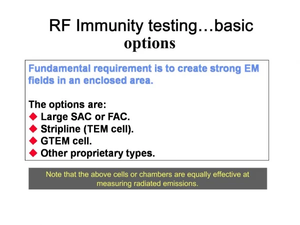
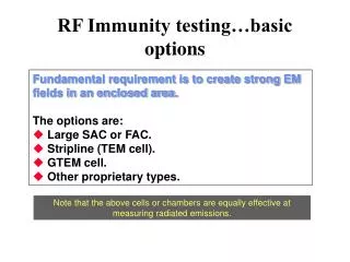
Resent Chip: RF Sampling Frontend • Due to “PCB” we are not able to measure NF at high frequencies? • Traces are not even. • FR4 not good for >1GHz • Connector Pad parasitics & impedance discontinuities • Remedy: We are working on it …….. • New PCB with Rogers not FR4 or Thin Film Technology • TRL calibration
RF Testing- RF to DC Detector • Idea! Only from DC measurements. • All catastrophic faults can be detected. • Some of parametric faults. • Performance parameter like Gain, 1dB CP • And may be NF & IP3 • Calibration of Detectors with DC/Low voltage signals only
R e c e i v e r (zero-IF) Base Band Processor LPF ADC LNA TA Test xtest Q I I Q I Q LO DAC 900 LPF IQ offset mixer Amp T r a n s m i t t e r IQ test signal QPSK is the simplest implementation but others can be used as well RF Testing- Offset Loopback • Test setup using IQ offset mixer for shared LO Tx band Rx band f fTx fRx f
=160 RF Testing- Offset Loopback • Test setup using IQ offset mixer for shared LO Tx I Rx I Tx Q =160 =50 (skew) Rx Q
Future Planes • New board for complete Chip measurements. • Test for Transceivers with polar modulator (shared LO) multistandard Transceivers. (with Phillips) • On-Chip phase noise measurements