Download
1 / 19
190 likes | 191 Views
CE 382, Hydraulic Systems Design (pipes, pumps and open channels). Principles of hydraulics Conservation of energy (Bernullie) P1/ + V1^2/2g + Z1 = P2/ + V2^2/2g +Z2+ hf +hm -hp 2. Continuity (conservation of mass) 1.A1.V1 = 2.A2.V2 V1. A1 = V2. A2

E N D
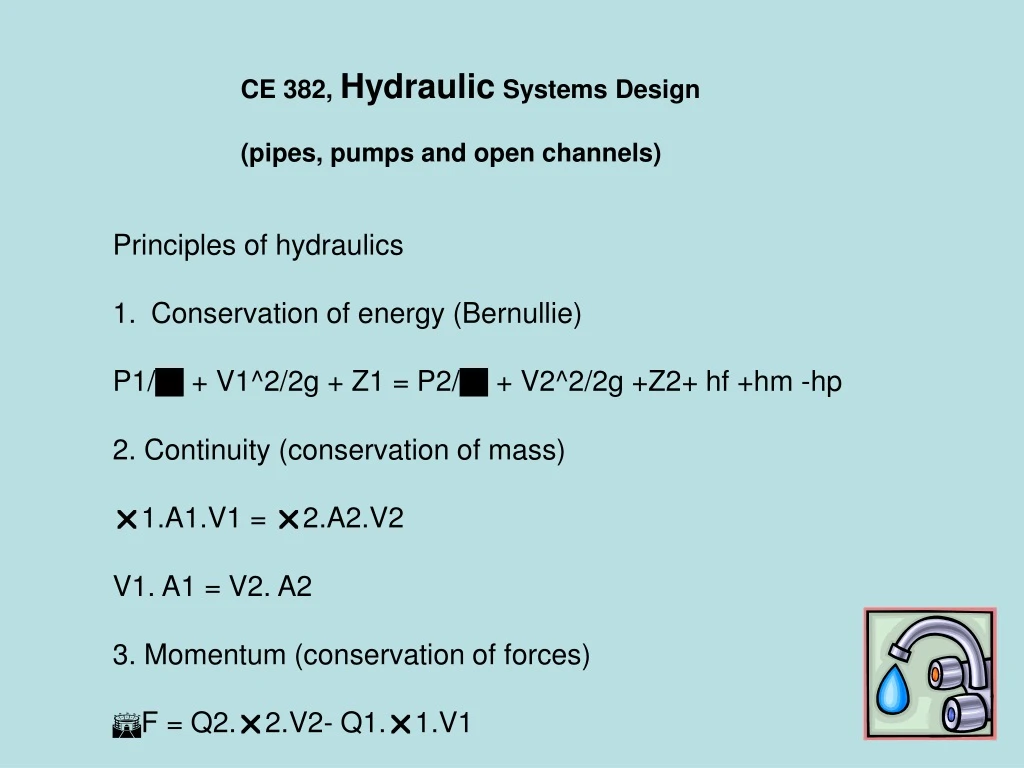
CE 382, Hydraulic Systems Design (pipes, pumps and open channels) • Principles of hydraulics • Conservation of energy (Bernullie) • P1/ + V1^2/2g + Z1 = P2/ + V2^2/2g +Z2+ hf +hm -hp • 2. Continuity (conservation of mass) • 1.A1.V1 = 2.A2.V2 • V1. A1 = V2. A2 • 3. Momentum (conservation of forces) • F = Q2.2.V2- Q1.1.V1
Methods How to calculate hf? Darcy-Weisbach eq.
NR or Re =V.D/ NR = Reynolds number V = velocity, L/T D= Inside Diameter, L = kinematic viscosity, L2/T = 1x10^-6 m2/s or 1.05x10^-5 ft2/s at 20 C
NR or Re = .V.D/µ • = fluid density, M/L3 V = velocity, L/T D = diameter, L µ = dynamic viscosity, F-T/L2
Colebrook’s eq. Swamee and Jain eq.
Hazen – William eq. V = k1.C.R^0.63.S^0.54 V = velocity, L/T C = roughness coefficient (table 3-2, p12) R = hydraulic radius, L S = Slope of energy grade line, L/L K1 = 0.849 for SI units K1 = 1.318 for USCS units
Hazen William, Conventional Units hf = friction loss, ft L = length, ft Q= flow, gpm D= diameter, inch
Hazen-William Conventional units Q =0.28 C.(D^2.62)(S^0.54) Q is in gpm D is in inches
Manning Q = k/n .A. R^2/3. S^1/2 Q discharge rate, L3/T K = 1.486 for USCS and 1.0 for metric unit n = Manning roughness coefficient (table 3.3, p13) R = Hydraulic radius, L S = Slope of energy grade line, L/L
Limitation of H-W eq, • Valid only for water • D> 5 cm • V<3 m/sec
Quiz #1 How much water will flow to point C? If you want to reduce the flow, what would you do? Draw the EGL A B C Elev. A= 120 ft Elev. B= 115 ft Elev. C = 108 ft Pipe B-C: 6 inch steel, 1000 ft long f = 0.02
Solution with H-W: Ea = Ec +hf 0+0+120 = 0+V^2/2g + 115 + hf Assume v^2/2g = 0 C =150 V= 1.318(150)(0.5/4)^0.63(5/1000)^0.54 V =3.05 ft/s Q = V.A = 3.05 (3.14)(0.5)^2/4 = 0.6 ft3/s
Minor Losses 1. Sudden contraction hc = Kc (V2^2)/2g Kc from Table 3.4, p 15 If D2/D1 =0, Kc = 0.5
2. Gradual Contraction h’c = K’c (V2^2/2g) K’c = from figure 3.13, p 16 3. Entrance loss Water entering from reservoir into pipe he = Ke (V^2)/2g Ke from figure 3.14, p 16
4. Sudden enlargement he = (V1-V2)^2/2g 5. Gradual enlargement hE = KE (V1^2-V2^2)/2g KE from figure 3.16 , page 17
5. Loss due to bend hb = Kb .(v^2)/2g Kb for various R/D ration: from the table on Page 18. 6. Loss of head in Valves hv = Kv (V^2)/2g