Download
1 / 21
210 likes | 403 Views
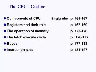
The CPU - Outline. Components of CPU Englander p. 166-167 Registers and their role p. 167-169 The operation of memory p. 170-176 The fetch execute cycle p. 176-177 Buses p. 177-183 Instruction sets p. 183-197 . CPU components.

E N D
The CPU - Outline. • Components of CPU Englander p. 166-167 • Registers and their role p. 167-169 • The operation of memory p. 170-176 • The fetch execute cycle p. 176-177 • Buses p. 177-183 • Instruction sets p. 183-197
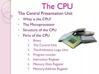
CPU components • Three major components of the CPU: ALU, Control unit, and Registers. • The Arithmetic Logic Unit (ALU) performs all calculations, operating on binary data with arithmetic and logical functions. • Arithmetic operations include additions, division, exponentials, logarithms. • Logical functions include comparisions (< > = ) and transformations
CPU components • Control Unit fetches and interprets instructions from memory, deciding what action has to be taken • Control Unit executes instructions that do not require logical or arithmetic operations eg JUMP or HALT instruction • Control Unit generates signals to coordinate all other CPU components, and moves data and instructions between registers.
CPU components • Registers - very fast memory providing temporary storage places for data and instructions. (May be in control unit or ALU. ) • Registers are often assigned special roles - eg the accumulator which holds the result of calculations. • Other important registers - • Program counter (instruction pointer)(PC) • Memory address register (MAR) • Memory data(buffer) register (MDR) • Program status register (PSW) • Instruction register (IR)
Program Counter ALU Accumulator Instruction Register CPU BUS BUS BUS Control Unit Control Unit BUS Primary Memory • Data is moved between CPU components and from memory into registers along buses - shared communication pathways
START Fetch the next instruction Execute the Instruction • The CPU operates by performing an Instruction Cycleconsisting of 2 main parts : Fetch+Execute. • CPU reads (fetches) instructions from memory • CPU decodes and ‘executes’ instruction.
Fetch-execute cycle • The fetched instruction is loaded in to the IR and the program counter (PC) keeps track of which instruction is to be fetched next. • A single instruction is broken down further into micro-instructions before it can be executed. For example it must initially be broken down into opcode and operands.
Fetch-execute cycle • Fetch-Execute Cycle: • Fetch • Program Counter -> Memory Address Register • Data -> Memory Data Register • Memory Data Register -> Instruction Register • Execute (load) • IR (op+address) -> Memory Address Register • Memory Data Register -> Accumulator • Program Counter + 1 -> PC
Instruction sets • Each CPU type has a unique collection of instructions which it can execute - known as its instruction set. • The instruction set must provide for: • Arithmetic e.g. + - * / • Comparisons e.g. < > = • Data movement e.g LOAD,STORE, MOVE • Program control e.g. JUMP, CALL, RETURN • Also instructions to implement boolean logic, operate on stacks, and multimedia data
System Clock • System clock generates regular pulses to synchronize all system events and determine the speed at which processing can occur. • Each fetch-execute instruction cycle divided into states, which are one clock pulse long. Most instructions require multiple steps, and so require several clock pulses to complete. • Some individual steps (e.g. a memory access) take longer & may require additional clock pulses to complete – these clock cycles spent waiting are called wait states
System Clock • The clock speed of a CPU determines how often a new instruction is executed, and is measured in MHz or GHz: 1.7GHz means that a computer executes 1,700,000,000 instructions per second! • However, all recent microprocessors overlap the fetching, decoding and execution of a number of instructions at same time. This is called pipelining. • Therefore, clock speed not necessarily an accurate measure of performance, and other measurements are required (to be covered later).
System Clock Evolution of Intel Microprocessors. Name: 8008 80386 80486 Pentium Pentium4 Year: 1972 1985 1989 1993 2000 I. set 66 154 235 >300 >400 Clock <1mh 33mh 50mh 133mh 1.3GH Speed
Memory addressing • The “address” is not the “data” • address bus • data bus • Size matters…. • 2, 4, 8, 16, 32, 64 bit address buses • M=2^k where k=the width of the address bus • Word size determined by bus and register size.
Types of memory • examples: • RAM - random access memory • DRAM - dynamic RAM, requires refresh • SRAM - static RAM, no refresh & faster • ROM - read only memory • PROM - programmable ROM • EPROM - erasable, programmable ROM
Buses • Data travels between components (CPU, memory & I/O devices) of the computer along communication paths called buses. (Note: can also have buses external to system) • Bus is made up of multiple lines, which may be wires or conductors on a printed board. • Bus may carry data between two components only (point-to-point) or it may be shared between many (multipoint). Need to control bus access in multipoint buses to prevent collisions between signals.
memory CPU ALU video controller Control unit disk controller Buses Point-to point bus Multipoint / system bus Buses may be serial (one bit at time) or parallel (multiple bits at time. Most internal buses are parallel, most external are serial.
Bus Lines • Bus lines classified as data, address, control and power lines. Depending on the function of the bus, it may have all or some of these types. • Current system bus will have >100 lines, including all 4 types • Data lines provide path for moving data (including instructions) between system components. It’s width usually same or multiple of CPU word size (eg 64 bit CPU usually has 64 or 128 bit data bus) to enhance system performance
Address lines used by the CPU to carry a digital code which uniquely identifies each memory location and I/O port. It’s size dictates maximum addressable memory. eg 8 bit address bus allows only 28 memory locations 1 or 0 00 01 10 11 2 line address BUS 1 or 0 Possible combinations = 4 (or 22 ) 00, 01, 10, 11 MEMORY LOCATIONS
Evolution of Intel Microprocessor Name: 8080 80286 80386 Pentium PII Year: 1974 1980 1985 1993 1997 Data Bus 8 16 32 64 64 Address 20 24 32 32 36 bus width Addressable 1MB 16MB 4GB 4GB 64G Memory
Bus lines • Control lines include • memory read/write & I/O read/write • transfer acknowledge • bus request/grant • interrupt request/acknowledge • clock used to synchronize operations • Bus clock speed and data bus width together determine theoretical max data transfer rate of bus eg 64 bits * 100 mhz • Power lines carry electrical power to the module they are communicating with.
Tutorial • Review Little-Man Computer • Review fetch-execute cycle • www.cems.uwe.ac.uk/~rstephen/courses/UQI108S1