Download
1 / 17
170 likes | 177 Views
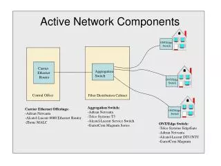
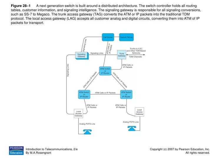
This figure showcases the architecture of a next generation switch that separates voice and data efficiently using a distributed architecture. It includes components like switch controller, signaling gateway, trunk access gateway, and local access gateway. The network topology includes ATM or IP networks, and MPLS is used to route packets. The figure also illustrates the use of line codes, DSL modems, DSLAMs, and broadband over power line networks.

E N D
Figure 28–1 A next generation switch is built around a distributed architecture. The switch controller holds all routing tables, customer information, and signaling intelligence. The signaling gateway is responsible for all signaling conversions, such as SS-7 to Megaco. The trunk access gateway (TAG) converts the ATM or IP packets into the traditional TDM protocol. The local access gateway (LAG) accepts all customer analog and digital circuits, converting them into ATM of IP packets for transport.
Figure 28–2 Data and voice information is separated in the transport network by placing voice information on one virtual circuit (VC) and the data on a second. (TAG = truck access gateway; LAG = local access gateway.)
Figure 28–3 The ATM network or IP network used to connect the TAGs, LAGs, and call server is similar to the currently deployed ATM or IP networks. The purpose of building a cell or packet network versus the traditional TDM network is to separate voice and data efficiently before hitting the switch. In addition, bandwidth savings are realized on statistically multiplexed networks such as ATM and IP. (VC = Virtual conduit.)
Figure 28–4 The LAG is able to separate the data and voice signals onto their own logical path. The switch does not deal with data.
Figure 28–5 The TAG accepts traffic in both directions—from the ILEC or other TDM network and from the next generation network. The TAG converts the various protocols such as ATM to TDM or TDM to ATM to interface both types of networks.
Figure 28–6 The dial tone Sarah hears when she picks up her phone is generated by the LAG that resides in her serving central office—Maple Street.
Figure 28–7 The advantage of using a next generation network to carry both voice and data, often referred to as a converged network. The TAG and call server are not involved when data traffic flows through the network. Dial-up data calls still must be routed via the routing tables housed in the call server.
Figure 28–8 The soft switch is used to route data traffic off the voice network.
Figure 28–9 The soft switch directs calls coming in from traditional analog POTS line and a modem.
Figure 28–10 Connecting two SONET fiber optic rings together only requires one SONET multiplexer at each of the interconnection points. New methods for connecting a node riding on a ring using an arc connection between the two are becoming very popular.
Figure 28–11 MPLS is becoming one of the most talked about protocols in the transport industry. MPLS provides a way to lessen the latency on IP routed networks. A tag is attached to each packet, similar to attaching a ZIP code to an address. The tag is used to route the packet through the network, eliminating the need for the router to crack open the IP frame and read the source and destination address. MPLS is one of the most promising protocols today.
Figure 28–12 The three most popular line codes used to transport information across digital subscriber lines:(a) 2B1Q line code (b) CAP line code (c) DMT line code
Figure 28–13 A DSL modem attached to a laptop computer. A CAP line code that provides an asymmetrical DSL service—higher downstream speed than upstream speed—is being used.
Figure 28–14 The deployment of DSLAMs in the local network produced alternative ways to provide dial tone to the business customer. One digital subscriber line provides numerous voice lines and a data connection.
Figure 28–15 IP services boxes are placed in the network and used to aggregate DSL traffic and route the information to the correct network. In addition to aggregating digital subscriber lines, the IP services box may offer special services such as firewalls.
Figure 28–16 Broadband over Power Line network topology takes advantage of the power lines that feed a neighborhood. As shown in the figure, the network topology is a combination of fiber optic cables and power lines. The term hybrid fiber/BPL is often used to describe the BPL network.
Figure 28–17 A power line interface device (PLID), also called a power line modem, is plugged into the AC outlet. The laptop or other computing device is connected via Ethernet cable to the PLID. The HomePlug signal rides on frequencies well above AC power signals, eliminating interference from the power feed.