Download
1 / 18
180 likes | 331 Views
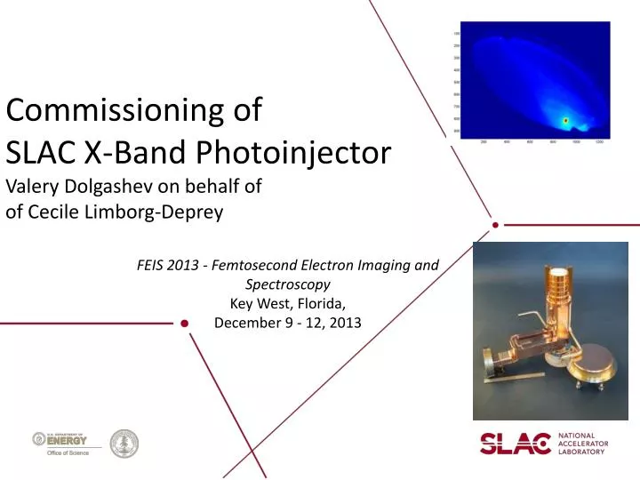
Commissioning of SLAC X-Band Photoinjector Valery Dolgashev on behalf of of Cecile Limborg- Deprey. FEIS 2013 - Femtosecond Electron Imaging and Spectroscopy Key West, Florida, December 9 - 12, 2013 . Acknowledgments . C.Adolphsen , T.Raubenheimer

E N D
Commissioning of SLAC X-Band PhotoinjectorValery Dolgashevon behalf ofof Cecile Limborg-Deprey • FEIS 2013 - Femtosecond Electron Imaging and Spectroscopy • Key West, Florida, • December 9 - 12, 2013
Acknowledgments • C.Adolphsen, T.Raubenheimer • NLCTA Team: C.Hast, D.Mc.Cormick , K.Jobe, M.Dunning , E.Hemsing, S.Weathersby, F.Fu • Faya Wang • RFARED team • A.Vlieks • Laser group: I.Makasyuk, A.Miahnahri, S.Gilevich, W.Polzin, P.Hering • Controls : Matjaz Kobal (Cosylab), M.Boyes, K.Luchini, D.Rogind • Mechanical: D.Walz, R.Rogers • Alignment: G.Gassner, H.Imfeld • Many other people (A.Benwell, B.McKee, J.Tice, bldg 33 team, Juan Cruz, C.Hudspeth, … )
Motivation: X-Band photoinjectorA high brightness electron source • Build upon decades of DOE investment into high-gradient rf technology • Mature high gradient R&D: • practical accelerating gradient for linacs ~100MV/m (25MV/m for S-Band) • practical cathode fields in RF gun for RF gun ~200MV/m (120MV/m for S-Band) Recent research in new materials is pushing practical surface fields toward 300 MV/m • Experience from success of LCLS and its RF photoinjector • Possible applications: • Injector for Compact, FELs (180 m long, 2fs, 20GW, 6GeV:PRST-AB,15, 030703 (2012)) • Compact Inverse Compton scattering (ICS) source • Ultra-Fast Electron Diffraction
High cathode electric fields: 200 MV/n X-band vs. 120 MV/m S-band S-band X-band Beta of 0.5 reached at 1 mm for X-band vs. 3 mm for S-band Accelerating electric field over the first 3 mm
RF Gun Simulations (Astra)Peak brightness: 8x higher for X-Band than S-Band gun • bunch length shorter by 3-4 • from high dEz/ dt • emittance smaller by up to 2 • from high higher cathode fields • larger surface field allows smaller laser spot, • and hence smaller transverse emittance
History of SLAC X-Band Guns • 5.5 cell gun was developed at SLAC for compact Inverse Compton Source in collaboration with UC Davis (2001-2005) (A.E. Vlieks, et al., SLAC-PUB-11689) • “Mark0” have improved coupler (racetrack and low-magnetic fields) – from 2012 operating at SLAC X-band Test Accelerator • “Mark 1” have increased mode separation, elliptical irises, 5.6 cell - collaboration SLAC/LLNL, now at Livermore (R.Marsh et al. Phys. Rev. ST Accel. Beams 15, 102001 –2012)
X-Band Test Area (XTA) in bunker of SLAC’s Next Linear Collider Test Accelerator Transverse deflector Gun + linac < 1.8m E = 80 MeV (soon 100MeV) YAG/OTR 6.7 m spectrometer
X-Band Test is operational since summer 2012 6 dB RF splitter High power phase shifter Linac Gun + Solenoid Laser Injection chamber +YAG +FC Laser Compressor(IR) Tripler
XTA rapid turn-on • 1st beam July 2012, 18 months after project started • Existing X-Band RF station and waveguide • Existing NLCTA tunnel and infrastructure in place • Imported LCLS control system & applications • During 1st year • Stabilization of beam timing jitter • Laser oscillator PLL: reduced noise from 500fs (2) to 160 fs (0.64 ) • RF feedbacks (phase, amplitude, SLED) • Recent beam-line upgrades • New, 100MV/m accelerating structure with race-track couplers • New Cavity BPMs
Experimental Results • Energy out of rf gun ~ 7.5MeV (VRF,peak~ 200MV/m) • Energy is 85 MeV at 1.8 m from source • Charge of up to 250 pC transmitted through linac • QE in low 10-5 • Peak current of 150A (for 120pC) • Bunch lengths • 250 fsrms at 20pC • 540 fs at 150 pC • Emittance : not fully optimized yet (unstable laser mode) ~ 0.7 mm-mrad for 30 pC • ~ 1.7 mm-mrad for 100 pC • Energy spread rms 3.10-4 (15 pC) , 10-3 (60 pC) • Energy jitter < 10-3
Cathode peak field 200MV/m operated routinely Schottky scan Time of Flight (TOF) Arrival time [ X-Band] Charge [a.u] [ X-Band] [ X-Band] Astra simulations 200MV/m also confirmed by steering measurement
Parasitic, field emission currents • 17.5 MW in gun, 209 MV/m on the cathode • Total field-emission charge ~180pC during 160ns long RF pulse Dark currents are at acceptable level Photo-e beam 13% Dark Current fluctuations correspond to power fluctuations at ~1% level Dark current
Commissioning: Emittance measurements and optimization ey ~ 0.7 mm-mrad at 20 pC ex ~ 0.9 mm-mrad at 20 pC But laser spot size was too large
Commissioning:Bunch length measurements • X-Band transverse deflector Deflector off Measured bunch compression at low Q 475+/-70 fsrms at 50 (15pC) 250+/-70 fsrms at 30 (10pC) 125+/-30 fsrms at 15 (5pC) Deflector on
Application of X-band injector to Ultrafast Electron Diffraction • Phase 1: Single-shot time resolved measurements, • using rf deflector to streak ps electron beam after sample • Phase 2: Stroboscopic measurement using short (~30 cm) standing wave accelerating cavity for velocity bunch-length compression
UED experiment at XTA – Phase 1 RF deflector , 200fs resolution R.Li Review of scientific instruments 81, 036110 2010 , Tsinghua University • - Streaked long ~1ps bunch to observe sub-ps dynamics • - very high resolution X-Band transverse deflector Gun (200MV/m) Deceleration in 1-m-long Traveling Wave linac E = 5.5 MeV, = 0.1 mrad x= 0.3 mm bTcav~ 8 m Resolution ~ 4 fs sx e sx'
UED experiment at XTA –phase 2 • Stroboscopic measurements with 7 fs-long-bunch • -install short Standing Wave accelerating to do velocity bunching • -use arrival time measurements to reconstruct timing • Early simulations at 1pC with compressor 7fs rms sx e sx'
Summary • X-Band Test Area is a test-bed for multiple techniques and methods that needed to make a compact, high brightness injector • Committing is ongoing with goal of sub-micron emittances and sub-ps-long bunches • Ultrafast Electron Diffraction is one of many potential applications of this technology