Download
1 / 54
570 likes | 883 Views
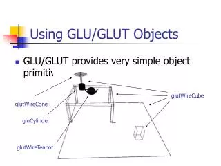
Geometric Objects in GLUT. GLUT geometric object commands have two forms: Solid: Renders a solid object. Wire: Renders an object in wire frame. GLUT geometric object commands do not generate texture coordinates except for the Teapot. Sphere.

E N D
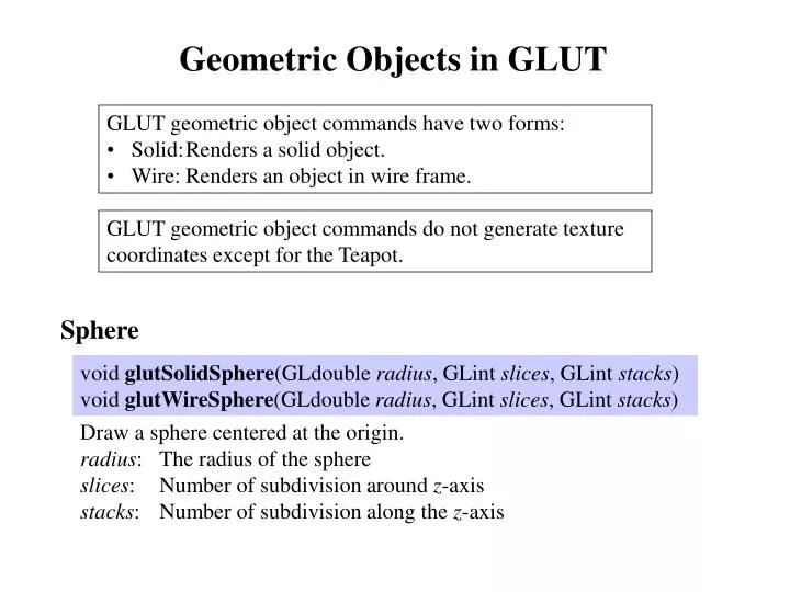
Geometric Objects in GLUT • GLUT geometric object commands have two forms: • Solid: Renders a solid object. • Wire: Renders an object in wire frame. GLUT geometric object commands do not generate texture coordinates except for the Teapot. Sphere void glutSolidSphere(GLdouble radius, GLint slices, GLint stacks) void glutWireSphere(GLdouble radius, GLint slices, GLint stacks) Draw a sphere centered at the origin. radius: The radius of the sphere slices: Number of subdivision around z-axis stacks: Number of subdivision along the z-axis
z z y y x x y z slices stacks x x
Cube void glutSolidCube(GLdouble size) void glutWireCube(GLdouble size) Draw a cube centered at the origin. size: Edge length of the cube z y x
Cone void glutSolidCone( GLdouble base, GLdouble height, GLint slices, GLint stacks) void glutWireCone( GLdouble base, GLdouble height, GLint slices, GLint stacks) Draw a cone. Base is at z = 0. Top is at z = height. base: The radius of the base of the cone. height: The height of the cone. slices: Number of subdivision around z-axis. stacks: Number of subdivision along the z-axis.
z y x z y x y z height (stacks) slices x x base
Torus void glutSolidTorus( GLdouble Rinner, GLdouble Router, GLint sides, GLint rings) void glutWireTorus( GLdouble Rinner, GLdouble Router, GLint sides, GLint rings) Draw a torus centered at the origin whose axis is z-axis. Rinner: Inner radius of the torus. Router: Outer radius of the torus. sides: Number of sides for each radial section. rings: Number of radial divisions for the torus.
z z y y x x y Router z Rinner x x sides rings
Teapot void glutSolidTeapot(GLdouble size) void glutWireTeapot(GLdouble size) Draw a Utah teapot, centered at the origin size: Relative size of the teapot. y x z
GLU Quadrics • Create a quadrics object. • Register error handling routine. • Specify rendering attributes for the quadrics object. • Render the quadrics object. • Delete the quadrics object when finished.
Managing Quadrics Objects GLUquadricObj * gluNewQuadric(void) Creates a new quadrics object and returns a pointer to it. void gluDeleteQuadric(GLUquadricObj * qobj) Delete a quadrics object and frees up its memory. void gluQuadricCallback(GLUquadricObj * qobj, GLenum which, void (*fn)(GLenum errorCode)) Define error handling callback function. qobj: Pointer to quadrics object which: Must be GLU_ERROR fn: Pointer to error handling function errorCode: Error code that is passed to error handling function.
Specify Attributes of Quadrics Objects void gluQuadricDrawStyle(GLUquadricObj * qobj, GLenum drawStyle) Specify drawing style of quadrics object qobj. void gluQuadricOrientation(GLUquadricObj * qobj, GLenum orient) Specify which side the quadrics surface normals point to. orient: GLU_OUTSIDE (default); GLU_INSIDE; For disk and partial disk, positive z side is considered outside.
void gluQuadricNormals(GLUquadricObj * qobj, GLenum normal) Specify how quadrics surface normals are generated. void gluQuadricTexture(GLUquadricObj * qobj, GLBoolean genTex) Specify whether texture coordinates are generated for the quadrics object. genTex: GL_FALSE (default); GL_TRUE;
Quadrics Primitives Sphere void gluSphere( GLUquadricObj * qobj, GLdouble radius, GLint slices, GLint stacks) Draw a sphere centered at the origin. radius: The radius of the sphere slices: Number of subdivision around z-axis stacks: Number of subdivision along the z-axis Texture coordinates: s changes linearly around z axis, ranges from 0.0 at +y axis, to 0.25 at +x axis, to 0.5 at –y axis, to 0.75 at –x axis, and back to 1.0 at +y axis. t changes linearly along longitudinal lines, ranges from 0.0 at z = –radius to 1.0 at z = radius.
Cylinder void gluCylinder( GLUquadricObj * qobj, GLdouble Rbase, GLdouble Rtop, GLdouble height, GLint slices, GLint stacks) Draw a cylinder oriented along z-axis. Base is at z = 0. Top is at z = height. Rbase: Base radius at z = 0. Rtop: Top radius at z = height. height: Height of the cylinder. slices: Number of subdivision around z-axis. stacks: Number of subdivision along the z-axis. Texture coordinates: s: The same as for a sphere. t changes linearly along z-axis, ranges from 0.0 at z = 0 to 1.0 at z = height. The cylinder is NOT closed at the base and the top.
z z Rtop slices height (stacks) y x Rbase x
Disk void gluDisk( GLUquadricObj * qobj, GLdouble Rinner, GLdouble Router, GLint slices, GLint rings) Draw a disk on the z = 0 plane. +z side is the outside. Rinner: Inner radius. Router: Outer radius. slices: Number of subdivision around z-axis. rings: Number of concentric rings. Texture Coordinates: y Rinner t Router 1.0 0.5 x rings slices s 0 0.5 1.0
Partial Disk void gluPartialDisk(GLUquadricObj * qobj, GLdouble Rinner, GLdouble Router, GLint slices, GLint rings, GLdouble Astart, GLdouble Asweep) Draw a partial disk (fan shape) on the z = 0 plane. Astart: Starting angle in degree Asweep: Sweep angle in degree. y 0 y Astart x 270 90 x Asweep 180
Bézier Curves and Surfaces Bézier curves Control points: Bézier blending functions (Bernstein polynomials) Binomial coefficients
Properties of binomial coefficients Iterative relationship of Bernstein polynomials
Bézier curve is one degree less than the number of control points.
Properties ofBézier curves Bézier curve lies within the convex hull of the control points.
Design Techniques ofBézier curves p3 p1 = p2 p3 p2 p0 p4 p1 p0 = p5 p4 Closed Bézier curve Duplicate control points to attract the curve
Connecting two Bézier curves pn-1 pn pn-2 p'0 p'3 p'1 p'2 C0p'0 = pn C1 p'1 = pn + (pn – pn-1) C2p'2 = pn-2 + 4(pn – pn-1)
CubicBézier curves n = 3. Four control points. Bézier matrix
Bézier surfaces pj,k : (m + 1) by (n + 1) control points m = 3, n = 3 m = 2, n = 2
OpenGL Evaluators OpenGL Evaluators are used to generate Bézier curves and surfaces. One-Dimensional Evaluators (Bézier Curves) Define One-Dimensional Evaluator void glMap1f( GLenum target, GLfloat u1, GLfloat u2, GLint stride, GLint order, const GLfloat *points) void glMap1d( GLenum target, GLfloat u1, GLfloat u2, GLint stride, GLint order, const GLdouble *points) u1, u2: Define range of parameter u1 u u2. order: Number of control points n+1. points: Array that stores coordinates of control points pk, k=0, 1, …, n stride: Offset between consecutive control point data in points.
To enable an evaluator, use glEnable(target); To disable an evaluator, use glDisable(target);
Evaluate One-Dimensional Evaluator void glEvalCoord1f(GLfloat u) void glEvalCoord1d(GLdouble u) void glEvalCoord1fv(GLfloat *u) void glEvalCoord1dv(GLdouble *u) Evaluate all enabled one-dimensional evaluators at parameter u.
Define One-Dimensional Mesh void glMapGrid1f(GLint m, GLfloat umin, GLfloat umax) void glMapGrid1d(GLint m, GLdouble umin, GLdouble umax) Define evenly spaced one-dimensional mesh in parametric space. u goes from umin to umax in m steps. Evaluate One-Dimensional Mesh void glEvalMesh1(GLenum mode, GLint i1, GLint i2) mode: GL_POINT or GL_LINE Equivalent to: if (mode == GL_POINT) mode2 = GL_POINTS; if (mode == GL_LINE) mode2 = GL_LINE_STRIP; glBegin(mode2); for (i = i1; i<=i2; ++i) glEvalCoord1f(umin + i * (umax – umin) / m); glEnd();
Two-Dimensional Evaluators (Bézier Surfaces) Define Two-Dimensional Evaluator void glMap2{fd}(GLenum target, GLfloat u1, GLfloat u2, GLint ustride, GLint uorder, GLfloat v1, GLfloat v2, GLint vstride, GLint vorder, const TYPE *points) u1, u2: Define range of parameter u: u1 u u2. uorder: Number of control points in u direction nu+1. ustride: Offset between consecutive control point data in u direction in points. v1, v2: Define range of parameter v: v1 v v2. vorder: Number of control points in v direction nv+1. vstride: Offset between consecutive control point data in v direction in points. points: 2D Array that stores coordinates of control points pi, j, i=0, 1, …, nu; j=0, 1, …, nv.
To enable an evaluator, use glEnable(target); To disable an evaluator, use glDisable(target);
Evaluate Two-Dimensional Evaluator void glEvalCoord2f(GLfloat u, GLfloat v) void glEvalCoord2d(GLdouble u, GLdouble v) void glEvalCoord2fv(GLfloat *value) void glEvalCoord2dv(GLdouble *value) Evaluate all enabled two-dimensional evaluators at parameter (u, v).
Normal generation: If a vertex coordinate evaluator (GL_MAP2_VERTEX_3 or GL_MAP2_VERTEX_4) is enabled, then vertex normal is generated using the following procedure: • If automatic normal generation is enabled by glEnable(GL_AUTO_NORMAL), then the vertex normal is calculated analytically from Bézier surface equation. • If automatic normal generation is disabled, then the normal evaluated from GL_MAP2_NORMAL evaluator is used. • If GL_MAP2_NORMAL is not enabled, then the current normal defined by glNormal3*() command is used.
Define Two-Dimensional Mesh void glMapGrid2f( GLint mu, GLfloat umin, GLfloat umax, GLint mv, GLfloat vmin, GLfloat vmax) void glMapGrid2d( GLint mu, GLdouble umin, GLdouble umax, GLint mv, GLdouble vmin, GLdouble vmax) Define evenly spaced two-dimensional mesh in parametric space. u goes from umin to umax in mu steps. v goes from vmin to vmax in mv steps. Evaluate Two-Dimensional Mesh void glEvalMesh2(GLenum mode, GLint i1, GLint i2, GLint j1, GLint j2) mode: GL_POINT, GL_LINE or GL_FILL
GL_POINT GL_LINE GL_FILL glEvalMesh2() is equivalent to: mode == GL_POINT. Draw points at grid intersections. glBegin(GL_POINTS); for (i = i1; i<=i2; ++i) for (j = j1; j<=j2; ++j) { u = umin + i * (umax – umin) / mu; v = vmin + j * (vmax – vmin) / mv; glEvalCoord2f(u, v); } glEnd();
mode == GL_LINE. Draw lines along u and v directions. for (i = i1; i<=i2; ++i) { u = umin + i * (umax – umin) / mu; glBegin(GL_LINE_STRIP); for (j = j1; j<=j2; ++j) { v = vmin + j * (vmax – vmin) / mv; glEvalCoord2f(u, v); } glEnd(); } for (j = j1; j<=j2; ++j) { v = vmin + j * (vmax – vmin) / mv; glBegin(GL_LINE_STRIP); for (i = i1; i<=i2; ++i) { u = umin + i * (umax – umin) / mu; glEvalCoord2f(u, v); } glEnd(); }
mode == GL_FILL. Draw filled quads. for (i = i1; i<i2; ++i) { u1 = umin + i * (umax – umin) / mu; u2 = umin + (i+1) * (umax – umin) / mu; glBegin(GL_QUAD_STRIP); for (j = j1; j<=j2; ++j) { v = vmin + j * (vmax – vmin) / mv; glEvalCoord2f(u1, v); glEvalCoord2f(u2, v); glEnd(); }
B-Spline Curves and Surfaces • Advantages of B-Spline over Bézier curves: • Polynomial degree is independent of control point number. • Local control of curve shape. B-Spline Curves Control points: d is the order of the B-spline curve Blending function Bk, d (u) has degree d – 1
knot vector: A sequence of (n+d+1) non-decreasing values Cox-deBoor recursive formulation: Any term with denominator evaluated as zero is assigned the value zero.
Properties of blending functions: • Bk, d has degree d – 1 and Cd-2 continuity • Bk, d is non-zero over d subintervals uk uuk+d • Properties of B-Spline curve: • B-Spline is defined only in the interval ud-1 uun+1 • Each section is influenced by d control points, and lies within the convex hull of these control points. • Each control point affects the shape of at most d sections.
Uniform, Periodic B-Spline Curves Knot values have constant spacing: Blending functions are periodic Open Uniform B-Spline Curves The first d knot values are the same. The last d knot values are the same. The rest knot values have constant spacing. Example of knot values: {0, 0, 1, 2, 3, 3}, for n = 3 , d = 2 {0, 0, 0, 0, 1, 2, 2, 2, 2}, for n = 4 , d = 4
Properties of open uniform B-spline curve: • The curve passes through the first and the last control points. • The tangent vector at the first control point is parallel to the line connecting the first two control points. • The tangent vector at the last control point is parallel to the line connecting the last two control points. • When d = n + 1 the curve reduces to Bézier curve.
Non-uniform B-Spline Curves Any knot values as long as they satisfy uk uk+1 Knot multiplicity can produce subtle variations in curve shape and discontinuity. B-Spline Surfaces (n1 + 1) by (n2 + 1) control points.
Rational Spline Curves Rational function: Ratio of two polynomials. Rational Spline: Ratio of two spline functions. pk: Control points k: Weight factors • Advantages of rational spline over B-spline: • Exact representation of quadric curves (conics) • Invariant under perspective projection transformation (Transforming the curve is equivalent to transforming the control points) NURBs: Non-uniform Rational B-Spline
Homogeneous coordinate representations: (kxk, kyk, kzk, k) (k = 0, 1, 2, ... , n) can be seen as control points in homogeneous coordinates.
GLU NURBS • NURBS without trimming: • Create a NURBS object by calling gluNewNurbsRenderer(). • Use gluNurbsCallback() to register error handling routine. • Use gluNurbsProperty() to define rendering properties. • Call gluBeginCurve() or gluBeginSurface() to start rendering. • Call gluNurbsCurve() or to define NURBS curve or gluNurbsSurface() to define NURBS surface. • Call gluEndCurve() or gluEndSurface() to stop rendering. • Delete NURBS object by calling gluDeleteNurbsRenderer().
Managing NURBS Object GLUnurbsObj * gluNewNurbsRenderer(void) Create a new NURBS object void gluDeleteNurbsRenderer(GLUnurbsObj * nobj) Delete a NURBS object Handling NURBS Errors void gluNurbsCallback(GLUnurbsObj * nobj, GLenum which, void (*fn)(GLenum errorCode)) Define error handling callback function for NURBS. nobj: Pointer to NURBS object which: Must be GLU_ERROR fn: Pointer to error handling function errorCode: Error code that is passed to error handling function.
Define NURBS Rendering Properties void gluNurbsProperty( GLUnurbsObj *nobj, GLenum property, TYPE value) property = GLU_DISPLAY_MODE Specify how NURBS surface is rendered.
property = GLU_SAMPLING_METHOD Specify how NURBS surface is tessellated.