Download
1 / 42
440 likes | 563 Views
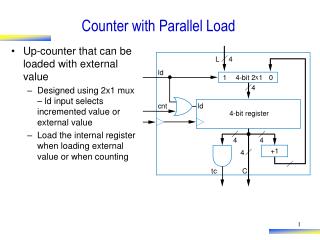
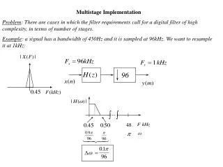
COUNTER CURRENT MULTISTAGE OPERATIONS WITH REFLUX. SINGLE-STAGE (FLASH) DISTILLATION. Distillate D, x D. UNECONOMICAL. IDEAL STAGE. Feed F, x F. Bottom Product B, x B. L 0. V 1. 1. V 2. L 1. 2. L 2. V 3. F, x F. 3. V 4. L 3. 4. L 4. V 5. 5. L 5. V 6.

E N D
COUNTER CURRENT MULTISTAGE OPERATIONS WITH REFLUX
SINGLE-STAGE (FLASH) DISTILLATION Distillate D, xD UNECONOMICAL IDEAL STAGE Feed F, xF Bottom Product B, xB
L0 V1 1 V2 L1 2 L2 V3 F, xF 3 V4 L3 4 L4 V5 5 L5 V6 Countercurrent multistage contact
Simple counter-current flow cannot give as complete a separation as required N = More concentrated L0 x0 is fixed by other consideration uneconomical Where does L0 come from?
C Condenser LC -qC D V1 L0 1 Enriching section m F-1 Multistage cascade with reflux at both ends for distillation F F F+1 p Stripping section N B Reboiler qS S
C LC -qC V1 D 1 V2 2 V3 3 F F ZERO REFLUX • No liquid returned to stage 1 • No condensation of V2 to supply liquid leaving stage 1 • The vapor leaving stage 1 would be the same quantity and composition of the vapor leaving stage 2. • The vapor leaving stage 2 would be the same quantity and composition of the vapor leaving stage 3. • Etc. Multistage cascade with no liquid reflux
No vapor returned to stage N • No vaporization of to supply vapor leaving stage N • The liquid leaving stage N would be the same quantity and composition of the liquid leaving stage N-1. • The liquid leaving stage N-1 would be the same quantity and composition of the liquid leaving stage N-2. • Etc. F F N-2 N-1 N B qS S If the vapor reflux were eliminated: Multistage cascade with no vapor reflux
EQUILIBRIUM STAGES Limits of Operability A fractionating column by its inherent nature has two limits of operation based upon reflux ratio: • Minimum reflux • Total reflux
MINIMUM REFLUX D • There is insufficient liquid returned to the column • There is only an infinitesimal change in vapor and liquid compositions through the plates. • Infinite number of plates would be needed. • Actual operation of a column below or at minimum reflux is impossible. L0 F B Schematic representation of minimum reflux operation
D = 0 F = 0 B = 0 TOTAL REFLUX • All condensate is returned to the column • It requires the least number of stages. • Practically no overhead product and no bottom product can be made and no feed is introduced. • It is possible to operate experimentally a fractionating column at total reflux when the system inventory is large and only very small samples of distillate and bottoms are removed. Schematic representation of total reflux operation
Nmin Total cost Optimum design at minimum cost $/unit product Equipment cost Operating cost Number of stages MINIMUM REFLUX VS TOTAL REFLUX Small reflux ratio • Greater number of plates • Greater investment cost Large reflux ratio • More coolant • More heating medium • Greater operating cost Schematic relationship between reflux ratio and number of stages
qD V1, y1, H1 L0 x0 h0 D xD hD L1, x1, h1 Quantitative Relationships - Enriching Section 1 2 Total condenser
MATERIAL BALANCE AROUND TOTAL CONDENSER Over-all: V1 = L0 + D (1) (2) Component i: (3) (4) (5)
ENTHALPY BALANCE AROUND TOTAL CONDENSER V1 H1 + qD = L0 h0 + D hD (6) The total heat removed in the condenser can be expressed in terms of heat per unit mass of distillate stream times the mass of stream. qD = D QD (7) V1 H1 + D QD = L0 h0 + D hD (8) Introducing eq. (1) into eq. (8) to eliminate D yields: V1 H1 + (V1 – L0) QD = L0 h0 + (V1 – L0) hD (9)
V1 H1 + (V1 – L0) QD = L0 h0 + (V1 – L0) hD (10) Introducing eq. (1) into eq. (8) to eliminate V1 yields: (11)
qD V1, y1, H1 D xD hD L0 x0 h0 L1, x1, h1 Vm+1 ym+1 Hm+1 Lm xm hm F MATERIAL BALANCE IN ENRICHING SECTION
Over-all: Vm+1 = Lm + D (12) Component i: (13) Introducing eq. (12) into eq. (13) to eliminate D results in (14)
Introducing eq. (12) into eq. (13) to eliminate Vm+1 results in: (15)
ENTHALPY BALANCE IN ENRICHING SECTION (16) Introducing eq. (12) into eq. (16) to eliminate D results in (17)
Introducing eq. (12) into eq. (16) to eliminate Vm+1 results in: (18)
D yD HD qD V1, y1, H1 L0 x0 h0 L1, x1, h1 MATERIAL AND ENTHALPY BALANCES AROUND PARTIAL CONDENSER Partial condenser
Over-all: (19) V1 = L0 + D (20) Component i: (21) (22)
ENTHALPY BALANCE: V1 H1 + qD = L0 h0 + D HD (24) The total heat removed in the condenser (qD) can be expressed in terms of heat per unit mass of distillate stream times the mass of stream. qD = D QD (25) V1 H1 + D QD = L0 h0 + D HD (26)
Replacing D in equation (26) with (V1 – L0): V1 H1 + (V1 – L0) QD = L0 h0 + (V1 – L0) HD (27)
Replacing V1 in equation (26) by (L0 + D): (L0 + D) H1 + D QD= L0 h0 + D HD (28)
MATERIAL BALANCE IN ENRICHING SECTION WITH PARTIAL CONDENSER qD D yD hD V1, y1, H1 L0 x0 h0 L1, x1, h1 m Vm+1 ym+1 Hm+1 Lm xm hm F
Over-all: Vm+1 = Lm + D (29) Component i: (30) D is eliminated from equation (30) by substituting D with (Vm+1 – Lm): (31)
Vm+1 is eliminated from equation (30) by substituting Vm+1 with Lm + D (32)
qD D xD hD V1, y1, H1 L0 x0 h0 L1, x1, h1 Vm+1 ym+1 Hm+1 Lm xm hm F ENTHALPY BALANCE IN ENRICHING SECTION
(33) D is eliminated from equation (33) by substituting D with Vm+1 – Lm (34)
Vm+1 is eliminated from equation (33) by substituting Vm+1 with Lm + D (35)
MATERIAL BALANCE IN STRIPPING SECTION F yp+1 Hp+1 xp hp B xB hB qB
Over-all: (36) Component i: (37) Replacing B in equation (37) with (38)
ENTHALPY BALANCE: (39) qB = B QB (40) (41)
MATERIAL & ENTHALPY BALANCES ABOUT REBOILER yN HN yN+1 HN+1 qB B xB hB
Over-all: (42) Component i: (43) Replacing B in equation (43) with (44)
Hp+1 yp+1 hp xp MATERIAL BALANCE AROUND THE FEED PLATE Vm+1 Hm+1 ym+1 Lm hm xm F = FV + FL
Over-all: (45) Component i: (46) (47) (48)
(49) If the feed is a saturated liquid, the last term in eq. (49) drops out. If the feed is a saturated vapor, the middle term on the right side of eq. (49) drops out.
ENTHALPY BALANCE AROUND THE FEED PLATE (50) (51) • If the feed is a saturated liquid, the last term in eq. (51) drops out. • If the feed is a saturated vapor, the middle term on the right side of eq. (51) drops out.
Enthalpies of Liquid and Vapor Streams In liquid mixture / solution the molal enthalpy of the mixture at a given T and P is the sum of the partial molal enthalpies of the components composing the mixture. (52) In “regular” / ideal mixtures: (53) For gaseous / vapor mixtures at normal T and P: (54)