Download
1 / 15
150 likes | 170 Views
Learn about data movement in microcomputer systems using ARM architecture, including addressing modes, big vs. little endian, and instruction representation. Understand how data is loaded, stored, and moved in CPU registers for processing.

E N D
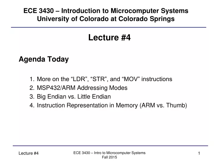
ECE 3430 – Introduction to Microcomputer SystemsUniversity of Colorado at Colorado Springs Lecture #4 Agenda Today • More on the “LDR”, “STR”, and “MOV” instructions • MSP432/ARM Addressing Modes • Big Endian vs. Little Endian • Instruction Representation in Memory (ARM vs. Thumb) ECE 3430 – Intro to Microcomputer Systems Fall 2015
Data Movement (How It Can Be Done) In all computer architectures, data must be moved into CPU registers for processing (an input operation) and moved out of the registers after processing (an output operation). The source and destination of the data can be memory external from the CPU, I/O peripherals, or other CPU registers. Some CPU architectures (such as ARM) use explicit “load” and “store” operations to move data into and out of CPU registers. These architectures are called load-store architectures. Other CPU architectures instead use strictly “move” instructions to accomplish both. All CPU architectures support a set number of addressing modes. These addressing modes define what the operands (if any) of an instruction represent. Recall operands provide additional information needed by an instruction. In the ARM processor, the source and destination addressing mode is either encoded in the 32-bit Instruction Code or suggested by the instruction itself. ECE 3430 – Intro to Microcomputer Systems Fall 2015
Data Movement (How It Can Be Done) The ARM CPU has a number of native addressing modes. They can be applied in various situations to different instructions: Register to register (Register direct): MOV R0, R1 ; R0 = R1 Absolute (Direct): LDR R0, MEM ; R0 = contents of memory Literal (Immediate): MOV R0, #15 ; R0 = 15 (decimal) ADD R1, R2, #12 ; R1 = R2 + 12 (decimal) Register indirect: STR R0, [R1] ; M(R1) = R0 Indexed: LDR R0, [R1, #4] ; R0 = M(R1+4) STR R0, [R1, R2] ; M(R1+R2) = R0 ECE 3430 – Intro to Microcomputer Systems Fall 2015
Data Movement (How It Can Be Done) Variations on Register indirect: LDR R0, [R1, R2, LSL #2] ; pre-scale R2 before adding to R1 ; R0 = M(R1 + 4*R2) <- fixed Variations on Indexed: In each of the following, R1 will change… LDR R0, [R1, #4]! ; first R1 = R1 + 4, then R0 = M(R1) LDR R0, [R1], #4 ; first R0 = M(R1), then R1 = R1 + 4 vs. LDR R0, [R1, #4] ; do not modify R1, R0 = M(R1 + 4) LDR R0, [R1, R2] ; do not modify R1 or R2, R0 = M(R1 + R2) ECE 3430 – Intro to Microcomputer Systems Fall 2015
Data Movement (How It Can Be Done) Some ways to use Indexed: LDR R0, [R1, #offset] ; Using general purpose register as a base address ; (or pointer) LDR R0, [PC, #offset] ; Using program counter as a base address – this ; is PC-relative addressing STR R0, [SP, #offset] ; Using stack pointer as a base address – this ; is useful for accessing data on the stack—relative ; to the top. You can use LDR or STR in any of the above examples. ECE 3430 – Intro to Microcomputer Systems Fall 2015
Data Movement (How It Can Be Done) Note that all of these are illegal: MOV R0, [R1, #offset] MOV [R1, #offset],R0 In ARM, MOV can only be used to copy registers (potentially with bits shifted) or initialize registers with immediate addressing. Whenever assembly operands are enclosed in square brackets, this implies memory is getting accessed—and this requires load or store operations. Remember: MOV instructions are always 32-bit. LDR and STR instructions (necessarily) can be 8, 16, or 32-bit. LDRB, LDRH, LDR. Can do sign-extension with LDRB and LDRH by adding an S (LDRSB and LDRSH)— since the destination (a register) is wider than the source. ECE 3430 – Intro to Microcomputer Systems Fall 2015
Data Movement (How It Can Be Done) • MOV is classified as a “data processing instruction” in ARM. • Other instructions that are classified the same: • ADD, SUB, CMP, AND, ORR, EOR, … • Not all 32-bit constants can be used with the MOV instruction. • Constants must follow one of these rules… • Constant that is produced by shifting an unsigned 8-bit value any number of bits (ARM). • Of this form: 0x00XY00XY (Thumb extension) • Of this form: 0xXY00XY00 (Thumb extension) • Of this form: 0xXYXYXYXY (Thumb extension) ECE 3430 – Intro to Microcomputer Systems Fall 2015
Data Movement (Manipulation While Moving) The ARM CPU pipeline actually contains a sneaky (but brilliantly placed) Barrel Shifter. A Barrel Shifter can shift a value any number of times—either direction—in a single clock cycle. The ARM CPU uses this rather than explicit shift instructions. Performing integer multiplication or division by powers of 2 only requires only shifting bits. Immediate values that you specify (#100 for example) have to be squeezed into the instruction code. Obviously not all bits are available—so the Barrel Shifter can generate the other constants mentioned in earlier slide. ECE 3430 – Intro to Microcomputer Systems Fall 2015
Data Movement (Initializing Registers) So, what if I want to initialize a register to 0x12345678? This won’t work: MOV R0, #0x12345678 Instead use: LDR R0, =0x12345678 When the assembler sees the above syntax, it will allocate the constant in program memory and then replace the syntax with a valid instruction: LDR R0, [PC, #offset] ; offset is the displacement to get to the constant ECE 3430 – Intro to Microcomputer Systems Fall 2015
Data Movement (Basic I/O) If I want to control an LED attached to an I/O port, I need to write to external memory locations that are associated with that port. For example, Port 1 is mapped to external address 0x40004C00. I need to write to that: LDR R0, =0x40004C00 ; R0 holds the port address MVN R1, #0 ; R1 contains all 1’s STRB R1, [R0] ; all 8 outputs of port 1 are now high MOV R1, #0 ; R1 contains all 0’s STRB R1, [R0] ; all 8 outputs of port 1 are now low ECE 3430 – Intro to Microcomputer Systems Fall 2015
Big Endian vs. Little Endian Suppose I wanted to do two 16-bit loads from memory locations 0x0000 and 0x0002… Big Endian (Motorola/Freescale Architectures, …): After a 16-bit load from 0x0000, I would see in CPU registers: 0x1234 After a 16-bit load from 0x0002, I would see in CPU registers: 0x5678 Little Endian (Intel Architectures and MSP432 and others): After a 16-bit load from 0x0000, I would see in CPU registers: 0x3412 After a 16-bit load from 0x0002, I would see in CPU registers: 0x7856 • Endian-ness applies to all memory accesses greater than 8-bits (i.e. 16-bit, 32-bit, 64-bit, 128-bit) • Generally speaking, higher-level programmers are insulated from these architectural differences. M(0000h)=12h M(0001h)=34h M(0002h)=56h M(0003h)=78h ECE 3430 – Intro to Microcomputer Systems Fall 2015
Further Explanation (ARM vs Thumb) In ARM, all instructions consist of a single instruction code. This code indicates the instruction mnemonic, the registers used, size of the transfer and in some cases, the immediate data. In traditional ARM architecture, the instruction code is always 32-bit. The program counter would be initialized to “point” to the address of the first instruction code. The instruction fetch cycle involves a 32-bit read across the MAB/MDB. Since the underlying memory system is byte-addressable, the program counter would advance by 4 to point to the next instruction code. Thumb is a compressed version of the ARM instruction set. Most Thumb instructions are 16-bit instead of 32-bit. By compressing the encoding, more instructions can fit into a smaller area of memory. The MSP432 uC uses the ARM Cortex-M4F CPU at the core. It always runs little endian and always uses the Thumb instructions (Thumb-2 included). For this reason, most but not all of the underlying ARM instruction set is available. ECE 3430 – Intro to Microcomputer Systems Fall 2015
Final Notes The program counter (PC) and status register (PSR) are not explicitly loaded with move instructions! The PC is initialized via reset interrupt vectors (discussed later) and the status register is modified automatically by the ALU as a result of instruction execution. In the ARM, the stack pointer (SP) is also initialized by a hardware vector (discussed later). It is not required that it be initialized if the system generates no interrupts and makes no use of subroutines (all discussed later). The link register (LR) should never be explicitly loaded. Other instructions use it and we’ll discuss that later. ECE 3430 – Intro to Microcomputer Systems Fall 2015
Final Notes Only use R0-R12 for general-purpose use. ECE 3430 – Intro to Microcomputer Systems Fall 2015
To Find Out More About MSP432/ARM/Thumb Instructions See the appendices of the text book (don’t worry about instructions we have not covered). ECE 3430 – Intro to Microcomputer Systems Fall 2015