Download
1 / 29
320 likes | 577 Views
Hubs, Switches and Bridges. CPSC 441 Tutorial TA : Fang wang. Parts of the slides contents are courtesy of the following people: Jim Kurose, Keith Ross: http://www.aw-bc.com/kurose_ross/ Yishay Mansour: http://www.cs.tau.ac.il/~mansour/networking-course/Icc3.ppt. LAN interconnection.

E N D
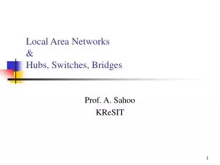
Hubs, Switches and Bridges CPSC 441 Tutorial TA: Fang wang Parts of the slides contents are courtesy of the following people: Jim Kurose, Keith Ross: http://www.aw-bc.com/kurose_ross/ Yishay Mansour: http://www.cs.tau.ac.il/~mansour/networking-course/Icc3.ppt
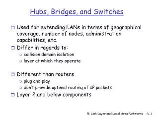
LAN interconnection • We need to break down big networks to sub-LANs • Limited amount of supportable traffic: on single LAN, all stations must share bandwidth • Limited length: 802.3 (Ethernet) specifies maximum cable length. For 10 Mbps: • Maximum length of the wire: 2,500 meter • Large “collision domain” (can collide with many stations)
twisted pair hub HUBS • Physical Layer devices • Essentially repeaters operating at bit levels: repeat received bits on one interface to all other interfaces • Hubs can be arranged in a hierarchy (or multi-tier design), with backbone hub at its top • Each connected LAN referred to as LAN segment
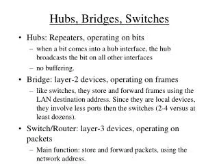
Hubs: Pros • Hub Advantages: • simple, inexpensive device • Multi-tier provides graceful degradation: portions of the LAN continue to operate if one hub malfunctions • extends maximum distance between node pairs (100m per Hub) • limitations : Hubs do not isolate collision domains: node may collide with any node residing at any segment in LAN • Single collision domain results in no increase in max throughput • multi-tier throughput same as single segment throughput • Individual LAN restrictions pose limits on number of nodes in same collision domain and on total allowed geographical coverage • cannot connect different Ethernet types (e.g., 10BaseT and 100baseT) Why?
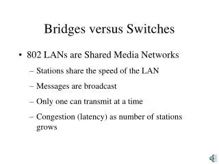
Bridges • Link-layer devices: • store, forward Ethernet frames • examine incoming frame’s MAC address, selectively forward frame based on its destination.When frame is to be forwarded on segment, bridge uses CSMA/CD to access segment and transmit • Advantages: • Isolates collision domains resulting in higher total max throughput, and does not limit the number of nodes nor geographical coverage • Can connect different type Ethernet since it is a store and forward device • Transparent: no need for any change to hosts LAN adapters
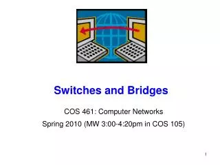
Switches • A switch could be considered a bridge with numerous ports. A bridge only has one incoming and one outgoing port. • Switch or Layer 2 switch is often used interchangeably with bridge • Plug-and-play, self-learning • switches do not need to be configured
Switch: allows multiple simultaneous transmissions A • hosts have dedicated, direct connection to switch • switches buffer packets • Ethernet protocol used on each incoming link, but no collisions; full duplex • each link is its own collision domain • switching:A-to-A’ and B-to-B’ simultaneously, without collisions • not possible with dumb hub C’ B 1 2 3 6 4 5 C B’ A’ switch with six interfaces (1,2,3,4,5,6)
Switch Table A • Q: how does switch know that A’ reachable via interface 4, B’ reachable via interface 5? • A: each switch has a switch table, each entry: • (MAC address of host, interface to reach host, time stamp) • looks like a routing table! • Q: how are entries created, maintained in switch table? • something like a routing protocol? C’ B 1 2 3 6 4 5 C B’ A’ switch with six interfaces (1,2,3,4,5,6)
Source: A Dest: A’ MAC addr interface TTL 60 1 A A A’ Switch: self-learning • switchlearns which hosts can be reached through which interfaces • when frame received, switch “learns” location of sender: incoming LAN segment • records sender/location pair in switch table A C’ B 1 2 3 6 4 5 C B’ A’ Switch table (initially empty)
Switch: frame filtering/forwarding When frame received: 1. record link associated with sending host 2. index switch table using MAC dest address 3. if entry found for destinationthen { if dest on segment from which frame arrivedthen drop the frame else forward the frame on interface indicated } else flood forward on all but the interface on which the frame arrived
Source: A Dest: A’ A’ A MAC addr interface TTL 60 60 4 1 A’ A A A’ A A’ A A’ A A’ A A’ A A’ Self-learning, forwarding: example A • frame destination unknown: C’ B flood 1 2 3 6 • destination A location known: 4 5 selective send C B’ A’ Switch table (initially empty)
S4 S3 S2 F I D H G E Interconnecting switches • switches can be connected together S1 A C B • Q: sending from A to F - how does S1 know to forward frame destined to F via S4 and S2? • A: self learning! (works exactly the same as in single-switch case!)
B 2 2 A , 1 A , 1 2 1 1 A What will happen with loops? • Incorrect learning S1 S2
Spanning Trees • Allow a path between every LAN without causing loops (loop-free environment) • Bridges communicate with special configuration messages (BPDUs- Bridge Protocol Data Units ) • Standardized by IEEE 802.1D • Requirements: • Each bridge is assigned a unique identifier • A broadcast address for bridges on a LAN • A unique port identifier for all ports on all bridges • MAC address • Bridge id + port number
Example Spanning Tree B8 B3 B5 B7 B2 B1 B6 B4
Spanning Tree Algorithm:overview 1. Determine the rootbridge among all bridges 2. Each bridge determines its root port • The port in the direction of the root bridge 3. Determine the designated bridge on each LAN • The bridge which accepts frames to forward towards the root bridge • The frames are sent on the root port of the designated bridge
Example Spanning Tree B8 B3 • Protocol operation: • Picks a root • For each LAN, picks a designated bridgethat is closest to the root. • All bridges on a LANsend packets towards the root via the designated bridge. B5 Root port B7 B2 B1 Root Designated Bridge B6 B4
Example Spanning Tree B8 Spanning Tree: B3 B5 B1 Root port B7 B2 B2 B4 B5 B7 B1 Root B8 Designated Bridge B6 B4
Spanning Tree Algorithm:Selecting Root Bridge • Initially, each bridge considers itself to be the root bridge • Bridges send Bridge Protocol Data Unit (BPDU) frames to its attached LANs • BPDUs frames contain information regarding the Swithch ID, originating switch port, MAC address, switch port priority, switch port cost etc • Best one wins • (lowest root ID/cost/priority)
Spanning Tree Algorithm:Selecting Root Ports • Each bridge selects one of its ports which has the minimal cost to the root bridge • When multiple paths from a bridge are least-cost paths, the chosen path uses the neighbor bridge with the lower bridge ID. The root port is thus the one connecting to the bridge with the lowest bridge ID. • In case of another tie, two bridges are connected by multiple cables. In this case, the lowest port ID is used
Select Designated BridgesForwarding/Blocking state • Same as selecting the root bridge: • Initially, each bridge considers itself to be the designated bridge, send BDPU frames to attached LANs, best one wins! • Root and designated bridges will forward frames to and from their attached LANs • All other ports are in the blocking state
Spanning Tree Protocol: Execution B8 B3 B5 B7 B2 B1 (B1,root=B1,dist=0) (B1,root=B1, dist=0) B6 B4 (B4, root=B1, dist=1) (B6, Root=B1dist=1)
Spanning Tree Protocol: Execution 1. An example network. The numbered boxes represent bridges (the number represents the bridge ID). The lettered clouds represent network segments.
Spanning Tree Protocol: Execution 2. The smallest bridge ID is 3. Therefore, bridge 3 is the root bridge.
Spanning Tree Protocol: Execution 3. Assuming that the cost of traversing any network segment is 1, the least cost path from bridge 4 to the root bridge goes through network segment c. Therefore, the root port for bridge 4 is the one on network segment c.
Spanning Tree Protocol: Execution 4. The least cost path to the root from network segment e goes through bridge 92. Therefore the designated port for network segment e is the port that connects bridge 92 to network segment e.
Spanning Tree Protocol: Execution 5. This diagram illustrates all port states as computed by the spanning tree algorithm. Any active port that is not a root port or a designated port is a blocked port.
Spanning Tree Protocol: Execution 6. After link failure the spanning tree algorithm computes and spans new least-cost tree. From: http://en.wikipedia.org/wiki/Spanning_Tree_Protocol
Switches vs. Routers • both store-and-forward devices • routers: network layer devices (examine network layer headers) • switches are link layer devices • routers maintain routing tables, implement routing algorithms • switches maintain switch tables, implement filtering, learning algorithms