Download
1 / 292
2.92k likes | 3.02k Views
Asset Categorization. Asawin Rajakrom. Course Syllabus.

E N D
Asset Categorization Asawin Rajakrom
Course Syllabus This course describes how the power distribution network assets are modeled and categorized into classes and draw a relationships among those classes. The class attribute represents a network data that will be used for inducing asset conditions, costs, probability of network failure as well as social and environment factors that influence the asset investment decision. The modeling approach bases on the prominent a Common Information Model (CIM) modeling method that used for representing real-world objects and information entities exchanged within the value chain of the electric power industry. Underpinning the CIM knowledge representation are several methods and methodologies such as UML, XML, and RDF. The course provides all necessary background of these technologies. In addition, engineering disciplines such as knowledge engineering and ontological engineering which emphasizes the knowledge acquisition and ontology development are also explicated. Combining them all together, attendees will equip themselves with all necessary knowledge to model not just power distribution system assets but all the other area of knowledge modeling.
Course Outline • Categorization principle & terminologies • Unified modeling language • eXtensible markup language • Resource description framework • Common information model • knowledge engineering • Ontological development • Power distribution network asset categorization
Asset Categorization Categorization Principle & Terminologies
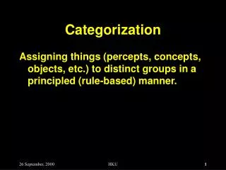
Categorization Overview • The basic cognitive process of arranging into classes or categories • The process in which ideas and objects are recognized, differentiated and understood. Categorization implies that objects are grouped into categories, usually for some specific purpose. Ideally, a category illuminates a relationship between the subjects and objects of knowledge • The function of category systems and asserts that the task of category systems is to provide maximum information with the least cognitive effort • The structure of the information so provided and asserts that the perceived world comes as structured information rather than as arbitrary or unpredictable attributes
Controlled Vocabulary • Way of describing a concept under a single word or phrase • May vary in its definition and usage when use in different domain • An established list of standardized terms used for both indexing and retrieval of information • The list of terms should be controlled by and be available from a controlled vocabulary registration authority in order to make a it unambiguous, non-redundant
Controlled Vocabulary At a minimum, the following two rules should be enforced to make true in practice: • If the same term is commonly used to mean different concepts in different contexts, then its name is explicitly qualified to resolve this ambiguity. • If multiple terms are used to mean the same thing, one of the terms is identified as the preferred term in the controlled vocabulary and the other terms are listed as synonyms or aliases.
Classification • Systematic arrangement in groups or categories according to established criteria • Act or process of putting people or things into a group or class • Establishing the correct class (or category) for an object where an object needs to be characterized in terms of class to which it belongs
Classification • Classification is an approach to systematically arranging objects into categories according to established criteria. • Objects are the physical and conceptual things we find in the universe around us: Hardware, software, documents, animals, human beings, and even concepts. • Classification allows to us manage things easily by grouping them into certain category under specific criteria and then manipulate against established condition.
Taxonomy • An orderly classification of plants and animals according to their presumed natural relationships • A hierarchy created according to data internal to the items in that hierarchy • An orderly classification of objects into hierarchical structure using a parent-child relationships • Using parent-child relationships in taxonomy: e.g., whole – part, genus – species, type – instance, or class – subclass. • Differ from classification in the sense that it classifies in a structure according to some relation between the entities and that a classification uses more arbitrary (or external) grounds
Ontology • A branch of metaphysics concerned with the nature and relations of being • A system of concepts used as building blocks of an information processing system • Consists of concepts, hierarchical (is-a) organization of them, relations among them, in addition to is-a and part-of, axioms to formalize the definitions and relations. • An explicit specification of a conceptualization
Ontology • Taxonomy and ontology are often interchangeably used, however they are fundamentally different. • Taxonomy classifies objects in a domain in hierarchical structure • give exact names for everything in a specified domain • show which things are parts of other things • Ontology offers more by expressing meaningful content within a specified domain of interest. • Has strict, formal rules (a "grammar") about those relationships that let us make meaningful, precise statements about our entities/relationships • A formal ontology is hence a controlled vocabulary expressed in an ontology representation language
Meta-model • Data about data • Facilitate the understanding, characteristics, and management usage of data • An explicit model of the constructs and rules needed to build specific models within a domain of interest • A valid meta-model is an ontology, but not all ontologies are modeled explicitly as meta-models • Schema is Metadata
Power Distribution System Asset Categorization • Provide all key attributes of network assets, either concrete or abstract, operational stresses and external environments for determining asset conditions and failure probability • Provide all key attributes to deduce asset costs • Provide all associated social and environment factors that influence decision of asset investment • This information is modeled into classes and attributes as well as class relationships using the common information model (CIM) specification
UML Unified Modeling Language
Origins of UML • Evolution of object-oriented technology:- • Develop and start using OOP language • Use of OOAD in business process modeling, requirement analysis and software systems design • UML was designed to bring together the best features of a number of analysis and design technologies and notations to produce and industrial standard.
What is UML? • UML is a visual language that originally applied in developing software systems. • Now is extended for using in other area like knowledge modeling. • It is a specification language. • it has a set of elements and a set of rules that determine how it can be used. • Most of UML elements are graphical: lines, rectangles, ovals and other shapes, and many of these graphical elements are labelled with words that provides additional information.
Why use UML? • The needs of modeling: Modeling can be as straightforward as drawing a flowchart listing the steps carried out in business process. • Readability brings clarity—ease of understanding. This involves knowing what a system is made up of, how it behaves, and so forth. • Reusability is the byproduct of making a system readable. After a system has been modeled to make it easy to understand, we tend to identify similarities or redundancy, be they in terms of functionality, features, or structure. • The underline is standardization.
UML Concepts UML is used to: • Show main functions and boundaries in a system using use cases and actors. • Illustrate use case realizations using interaction diagrams. • Represent a static structure of a system using class diagrams. • Modelling object behaviour using state diagrams. • Show implementation of the physical architecture using component and deployment diagrams. • Enhance the functionality using stereotypes.
UML Diagrams and Elements • Use case diagrams • Static structural diagrams • Class, object • Interaction diagrams • Sequence, collaboration • State diagrams • Activity diagrams • Implementation diagrams • Packages, Components, Deployment
Use Cases Diagram • Use cases diagrams describes the behavior of the target system from an external point of view. Use cases describe "the meat" of the actual requirements. • Use cases: A use case describes a sequence of actions that provide something of measurable value to an actor and is drawn as a horizontal ellipse. • Actors: An actor is a person, organization, or external system that plays a role in one or more interactions with your system. Actors are drawn as stick figures. • Associations: Associations between actors and use cases are indicated by solid lines. An association exists whenever an actor is involved with an interaction described by a use case
Class Diagram • Class diagrams show the classes of the system, their inter-relationships, and the operations and attributes of the classes • Explore domain concepts in the form of a domain model. • Analyze requirements in the form of a conceptual/analysis model • Depict the detailed design of object-oriented or object-based software
Person - TaxIDNo : String - Name : String + Income : double + TaxPaid : Boolean + calcTax() + calcTaxBal() Class Diagram Class name Person Attributes attribute name : type Operations operation name(parameter : type) : result type
Object Diagram • Object diagrams (instance diagrams), are useful for exploring real world examples of objects and the relationships between them. It shows instances instead of classes. They are useful for explaining small pieces with complicated relationships, especially recursive relationships.
Class and Objects City Name : String = default Country : String = default Population : integer = default setName (s : String = deault) setPopulation(p : integer = default) <<instanceOf>> <<instanceOf>> <<instanceOf>> New York : City Sydney : City London : City Name = London Name = New York Name = Sydney Country = USA Country = Australia Country = UK Population =2,324,320 Population =5,734,012 Population =3,536,000
Sequence Diagram • Sequence diagrams models the collaboration of objects based on a time sequence. It shows how the objects interact with others in a particular scenario of a use case.
Collaboration Diagram • Collaboration (Communication) diagrams used to model the dynamic behavior of the use case. When compare to Sequence Diagram, the Communication Diagram is more focused on showing the collaboration of objects rather than the time sequence.
State Diagram • State diagrams can show the different states of an entity also how an entity responds to various events by changing from one state to another. The history of an entity can best be modeled by a finite state diagram.
Activity Diagram • Activity diagrams helps to describe the flow of control of the target system, such as the exploring complex business rules and operations, describing the use case also the business process. It is object-oriented equivalent of flow charts and data-flow diagrams (DFDs).
Packages Diagram • Package diagrams simplify complex class diagrams, it can group classes into packages. A package is a collection of logically related UML elements. Packages are depicted as file folders and can be used on any of the UML diagrams.
Components Diagram • Component diagrams shows the dependencies among software components, including the classifiers that specify them (for example implementation classes) and the artifacts that implement them; such as source code files, binary code files, executable files, scripts and tables.
Deployment Diagram • Deployment diagram depicts a static view of the run-time configuration of hardware nodes and the software components that run on those nodes. Deployment diagrams show the hardware for your system, the software that is installed on that hardware, and the middleware used to connect the disparate machines to one another.
UML Class Diagrams and Relationships How would you draw a family tree? The steps you would take would be: • Identify the main members of the family • Determine how they are related to each other • Identify the characteristics of each family member • Find relations among family members • Decide the inheritance of personal traits and characters
UML Class Diagrams and Relationships • By definition, a class diagram is a diagram showing a collection of classes and interfaces, along with the collaborations and relationships among classes and interfaces. • A class diagram consists of a group of classes and interfaces reflecting important entities of the business domain of the system being modeled, and the relationships between these classes and interfaces. • A class diagram is a pictorial representation of the detailed system design.
Name Attributes Methods Elements of a Class Diagram