Download
1 / 14
1k likes | 2.31k Views
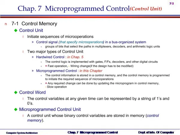
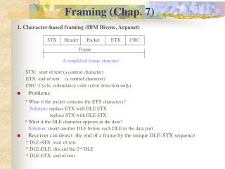
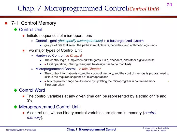
Chap. 7 Microprogrammed Control (Control Unit). 7-1 Control Memory Control Unit Initiate sequences of microoperations Control signal ( that specify microoperations ) in a bus-organized system groups of bits that select the paths in multiplexers, decoders, and arithmetic logic units

E N D
Chap. 7 Microprogrammed Control(Control Unit) • 7-1 Control Memory • Control Unit • Initiate sequences of microoperations • Control signal (that specify microoperations) in a bus-organized system • groups of bits that select the paths in multiplexers, decoders, and arithmetic logic units • Two major types of Control Unit • Hardwired Control : in Chap. 5 • The control logic is implemented with gates, F/Fs, decoders, and other digital circuits • + Fast operation,- Wiring change(if the design has to be modified) • Microprogrammed Control : in this Chapter • The control information is stored in a control memory, and the control memory is programmed to initiate the required sequence of microoperations • + Any required change can be done by updating the microprogram in control memory, - Slow operation • Control Word • The control variables at any given time can be represented by a string of 1’s and 0’s. • Microprogrammed Control Unit • A control unit whose binary control variables are stored in memory (control memory).
Microinstruction : Control Word in Control Memory • The microinstruction specifies one or more microoperations • Microprogram • A sequence of microinstruction • Dynamic microprogramming :Control Memory = RAM • RAM can be used for writing (to change a writable control memory) • Microprogram is loaded initially from an auxiliary memory such as a magnetic disk • Static microprogramming : Control Memory =ROM • Control words in ROM are made permanent during the hardware production. • Microprogrammed control Organization : Fig. 7-1 • 1) Control Memory • A memory is part of a control unit : Microprogram이 저장되어 있음 • Computer Memory (employs a microprogrammed control unit) • Main Memory : for storing user program (Machine instruction/data) • Control Memory : for storing microprogram (Microinstruction) • 2) Control Address Register • Specify the address of the microinstruction • 3) Sequencer (= Next Address Generator) • Determine the address sequence that is read from control memory • Next address of the next microinstruction can be specified several way depending on the sequencer input : p. 217, [1, 2, 3, and 4] User Program Machine Instruction Microprogram Microinstruction Microoperation
4) Control Data Register (= Pipeline Register ) • Hold the microinstruction read from control memory • Allows the execution of the microoperations specified by the control word simultaneously with the generation of the next microinstruction • RISC Architecture Concept • RISC(Reduced Instruction Set Computer) system use hardwired control rather than microprogrammed control : Sec. 8-8 • 7-2 Address Sequencing • Address Sequencing = Sequencer : Next Address Generator • Selection of address for control memory • Routine • Microinstruction are stored in control memory in groups • Mapping • Instruction Code Address in control memory(where routine is located) • Address Sequencing Capabilities : control memory address • 1) Incrementing of the control address register • 2) Unconditional branch or conditional branch, depending on status bit conditions • 3) Mapping process ( bits of the instructionaddress for control memory ) • 4) A facility for subroutine return
Selection of address for control memory : Fig. 7-2 • Multiplexer CAR Increment JMP/CALL Mapping Subroutine Return • CAR : Control Address Register • CAR receive the address from 4 different paths 1) Incrementer 2) Branch address from control memory 3) Mapping Logic 4) SBR : Subroutine Register • SBR : Subroutine Register • Return Address can not be stored in ROM • Return Address for a subroutine is stored in SBR
Opcode 1 0 1 1 Address • Conditional Branching • Status Bits • Control the conditional branch decisions generated in the Branch Logic • Branch Logic • Test the specified condition and Branch to the indicated address if the condition is met ; otherwise, the control address register is just incremented. • Status Bit Test 와 Branch Logic의 실제 회로 : Fig. 7-8 • 4 X 1 Mux 와 Input Logic(Tab. 7-4)으로 구성 • Mapping of Instruction : Fig. 7-3 • 4 bit Opcode = specify up to 16 distinct instruction • Mapping Process : Convertsthe 4-bit Opcode toa 7-bit control memory address • 1) Place a “0” in the most significant bit of the address • 2) Transfer 4-bit Operation code bits • 3) Clear the two least significant bits of the CAR (즉, 4 개의 Microinstruction 수용 가능) • Mapping Function : Implemented by Mapping ROM or PLD • Control Memory Size : 128 words (= 27) Computer Instruction Mapping bits 0 x x x x 0 0 Microinstruction Address 0 1 0 1 1 0 0
Subroutine • Subroutines are programs that are used by other routines • Subroutine can be called from any point within the main body of the microprogram • Microinstructions can be saved by subroutines that use common section of microcode • 예제)Memory Reference 명령에서 Operand의 Effective Address를 구하는 Subroutine • p. 228, Tab. 7-2에서INDRCT (여기에서 FETCH와 INDRCT는 Subroutine) • Subroutine은 ORG 64, 즉 1000000 - 1111111에 위치(Routine은 0000000 - 0111111) • Subroutine must have a provision for • storing the return address during a subroutine call • restoring the address during a subroutine return • Last-In First Out(LIFO) Register Stack : Sec. 8-7 • 7-3 Microprogram Example • Computer Configuration : Fig. 7-4 • 2 Memory : Main memory(instruction/data), Control memory(microprogram) • Data written to memory come from DR, and Data read from memory can go only to DR • 4 CPU Register and ALU : DR, AR, PC, AC, ALU • DR can receive information from AC, PC, or Memory (selected by MUX) • AR can receive information from PC or DR (selected by MUX) • PC can receive information only from AR • ALU performs microoperation with data from AC and DR (결과는 AC에 저장) • 2 Control Unit Register : SBR, CAR
Instruction Format • Instruction Format : Fig. 7-5(a) • I : 1 bit for indirect addressing • Opcode : 4 bit operation code • Address : 11 bit address for system memory • Computer Instruction : Fig. 7-5(b) • 16 명령어가 가능하며 4 개만 표시 • Microinstruction Format : Fig. 7-6 • 3 bit Microoperation Fields : F1, F2, F3 • 총 21개 Microoperation : Tab. 7-1 • 동시에 3 개의 microoperation 실행 가능 • 3 개 이하일 경우, 000(no operation)으로 채움 • two or more conflicting microoperations can not be specified simultaneously • 예제) 010 001 000 Clear AC to 0 and subtract DR from AC at the same time • Symbol DRTAC(F1 = 100) • stand for a transfer from DR to AC (T = to)
2 bit Condition Fields : CD • 00 : Unconditional branch, U = 항상 1 • 01 : Indirect address bit, I = DR(15) • 10 : Sign bit of AC, S = AC(15) • 11 : Zero value in AC, Z = AC = 0 • 2 bit Branch Fields : BR • 00 : JMP • Condition = 0 : • Condition = 1 : • 01 : CALL • Condition = 0 : • Condition = 1 : • 10 : RET • 11 : MAP • 7 bit Address Fields : AD • 128 word : 128 X 20 bit • Symbolic Microinstruction Label Field : Terminated with a colon ( : ) Microoperation Field : one, two, or three symbols, separated by commas CD Field : U, I, S, or Z BR Field : JMP, CALL, RET, or MAP 1 2 1 2 3 4 Save Return Address Restore Return Address •
15 14 11 10 …. … 0 I Opcode Address AD Field a. Symbolic Address : Label ( = Address ) b. Symbol “NEXT” : next address c. Symbol “RET” or “MAP” : AD field = 0000000 • ORG : Pseudoinstruction(define the origin, or first address of routine) • Fetch (Sub)Routine • Memory Map(128 words) : Tab. 7-2, Tab. 7-3 • Address 0 to 63 : Routines for the 16 instruction(현재는 4 instruction) • Address 64 to 127 : Any other purpose( 현재는 Subroutines : FETCH, INDRCT) • Microinstruction for FETCH Subroutine • Fetch Subroutine : address 64 Opcode Fetch Opcode Decode Instruction Format Operand Address Mapping
Symbolic Microprogram : Tab. 7-2 • The execution of MAP microinstruction in FETCH subroutine • Branch to address 0xxxx00 (xxxx = 4 bit Opcode) • ADD : 0 0000 00 = 0 • BRANCH : 0 0001 00 = 4 • STORE : 0 0010 00 = 8 • EXCHANGE : 0 0011 00 = 12, ( 16, 20, … , 60 ) • Indirect Address : I = 1 • Indirect Addressing : • AR이 지시하는 메모리 내용을 DR에 읽은 후, 다시 AR에 써 넣는다 • INDRCT subroutine • Execution of Instruction • ADD instruction 실행 절차 • 1) ADD 명령이 실행되면 FETCH subroutine에서 Opcode를 fetch한 후, MAP이 실행되면 MAP Process에 의해 CAR = 0 0000 00으로 branch 한다( 여기서 Opcode = 0000, Fig. 7-5(b) ) • 2) ADD 명령의 Address 0 에서는 CD 비트를 검사하여 Indirect = 1이면 INDRCT subroutine에서 Effective Address를 AR에 써넣고 Return 한다. • 3) ADD 명령의 Address 1 에서는 AR이 지시하는 Memory의 내용을 읽어서 DR에 써넣는다. • 4) ADD 명령의 Address 2 에서는 AC + DR을 AC에 저장한 후, FETCH subroutine으로 Branch하면 1)에서와 같은 방법으로 PC가 지시하는 명령어를 Fetch 하여 MAP 수행 결과에 따라 해당 Routine Address로 Branch 한다.
BRANCH instruction 실행 절차 • 1) BRANCH 명령의 Address 4 에서는 CD Bit를 검사하여 Sign(S) = 1 이면 Address 6 번으로 가서 Indirect를 검사하고 ARTPC에 의해 해당 Address로 Branch 한 후, FETCH에 의해 PC 가 지시하는 다음 명령을 수행한다. • 2) BRANCH 명령의 Address 4에서 Sign = 0 이면 Branch 하지 않고 FETCH에 의해 PC가 지시하는 다음 명령을 수행한다. • STORE instruction 실행 절차 • EXCHANGE instruction 실행 절차 • Binary Microprogram : Tab. 7-3 • Symbolic microprogram(Tab. 7-2) must be translated to binary either by means of an assembler program or by the user • Control Memory • Most microprogrammed systems use a ROM for the control memory • Cheaper and faster than a RAM • Prevent the occasional user from changing the architecture of the system • 7-4 Design of Control Unit • Decoding of Microinstruction Fields : Fig. 7-7 • F1, F2, and F3 of Microinstruction are decoded with a 3 x 8 decoder • Output of decoder must be connected to the proper circuit to initiate the corresponding microoperation (as specified in Tab. 7-1)
예제)F1 = 101 (5) : DRTAR F1 = 110 (6) : PCTAR • Output 5 and 6 of decoder F1 are connected to the load input of AR (two input of OR gate) • Multiplexer select the data from DR when output 5 is active • Multiplexer select the data from AC when output 5 is inactive • Arithmetic Logic Shift Unit • Control signal of ALU in hardwired control : p. 164, Fig. 5-19, 20 • Control signal will be now come from the output of the decoders associated with the AND, ADD, and DRTAC. From DR
Microprogram Sequencer : Fig. 7-8 • Microprogram Sequencer select the next address for control memory • MUX 1 • Select an address source and route to CAR • JMP 와 CALL의 차이점 • JMP : AD가 MUX 1의 2번을 통해 CAR로 전송 • CALL : AD가 MUX 1의 2번을 통해 CAR로 전송되고, 동시에 CAR + 1(Return Address) 이 LOAD 신호에 의해 SBR에 저장된다. • MUX 2 • Test a status bit and the result of the test is applied to an input logic circuit • One of 4 Status bit is selected by Condition bit (CD) • Design of Input Logic Circuit • Select one of the source address(S0, S1) for CAR • Enable the load input(L) in SBR • CAR + 1 • JMP/CALL • Mapping • Subroutine Return
Input Logic Truth Table : Tab. 7-4 • Input : • I0, I1 from Branch bit (BR) • T from MUX 2 (T) • Output : • MUX 1 Select signal (S0, S1) S1 = I1I0’ + I1I0 = I1(I0’ + I0) = I1 S0 = I1’I0’T + I1’I0T + I1I0 = I1’T(I0’ + I0) + I1I0 = I1’T + I1I0 • SBR Load signal (L) L = I1’I0T • CAR + 1 • JMP • CAR + 1 • CALL • MAP • RET CALL