Download
1 / 31
310 likes | 419 Views
BTeV Trigger. BEAUTY 2003 9 th International Conference on B-Physics at Hadron Machines Oct. 14-18, 2003, Carnegie Mellon University Michael Wang, Fermilab (for the BTeV collaboration). Fermi National Accelerator Laboratory. Tevatron. CDF. BTeV at C0. D0. p. p.

E N D
BTeV Trigger BEAUTY 2003 9th International Conference on B-Physics at Hadron Machines Oct. 14-18, 2003, Carnegie Mellon University Michael Wang, Fermilab (for the BTeV collaboration)
Fermi National Accelerator Laboratory Tevatron CDF BTeV at C0 D0 p p BTeV - a hadron collider B-physics experiment
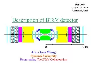
RICH SM3 Magnet Muon Straws & Si Strips EM Cal BTeV detector 30 Station Pixel Detector
sensor module 50 mm Multichip module 1 cm 400 mm 128 rows x 22 columns 5 cm Si pixel sensors 5 FPIX ROC’s 10 cm HDI flex circuit Wire bonds Sensor module 6 cm Pixel detector half-station Bump bonds Readout module Si pixel detector 14,080 pixels (128 rows x 110 cols) total of 23Million pixels in the full pixel detector 380,160 pixels per half-station
p K K B decay vertex K Bs Ds
L1 vertex trigger algorithm • Two stage trigger algorithm: • Segment finding • Track/vertex finding 1) Segment finding stage: Use pixel hits from 3 neighboring stations to find the beginning and ending segments of tracks. These segments are referred to as triplets
Segment finding: inner triplets 1a) Segment finding stage: phase 1 Start with inner triplets close to the interaction region. An inner triplet represents the start of a track.
Segment finding: outer triplets Track/vertex finding 1b) Segment finding stage: phase 2 Next, find the outer triplets close to the boundaries of the pixel detector volume. An outer triplet represents the end of a track.
Track/vertex finding 2a) Track finding phase: Finally, match the inner triplets with the outer triplets to find complete tracks. • 2b) Vertex finding phase: • Use reconstructed tracks to locate interaction vertices • Search for tracks detached from interaction vertices
Generate Level-1 accept if “detached” tracks going into the instrumented arm of the BTeV detector with: (GeV/c)2 cm Trigger decision Execute Trigger
7.6 MHz 800 GB/s BTeV trigger overview L1 rate reduction: ~100x L2/3 rate reduction: ~20x 4 KHz
FPGA segment finders Switch: sort by crossing number track/vertex farm (~2500 processors) Merge Trigger decision to Global Level 1 Level 1 vertex trigger architecture 30 station pixel detector
Collision Hall Counting Room to neighboring FPGA segment finder Pixel stations Data combiners FPGA segment finder Pixel processor Pixel processor Pixel processor DCB DCB DCB Optical links Pixel processor to neighboring FPGA segment finder Chip ID (13bits) sync (1bit) FPIX2 Read-out chip Row (7bits) Column (5bits) BCO (8bits) ADC (3bits) Pixel data readout time-stamp expansion time ordering clustering algorithm xy table lookup
Use only hits in inner region of N-1 L1 segment finder hardware Is there a hit? Matching hit? Matching hit? Within beam hole? Matching hit? Project to non-bend plane N+1 Project to non-bend plane N Look at non-bend plane N Project to non-bend plane Look at non-bend plane N+1 Start with bend view hits on N-1 and N Now look at non-bend plane N-1 Project downstream Project upstream
L1 segment finder on PTA card Uses Altera APEX EPC20K1000 instead of EP20K200 on regular PTA Modified version of PCI Test Adapter card developed at Fermilab for testing hardware implementation of 3-station segment finder (a.k.a. “Super PTA”)
L1 track/vertex farm hardware Block diagram of pre-prototype L1 track/vertex farm hardware
CMC connectors Buffer Manager FPGA FIFO 32-bit input 32-bit output L1 trigger pre-prototype board
Hitachi serial consoles Hitachi programming CF/LCD FPGA ArcNet ArcNet GL1/HPI FPGA Hitachi H8S Hitachi H8S FPGA boot device McBSP TI C6711 McBSP L1 pre-prototype with DSP mezzanine cards
L1 trigger pre-prototype test stand Hitachi programming Xilinx programming cable ArcNet serial console PCI test adapter TI DSP JTAG emulator
Level 2/3 trigger R&D 24-port fanout switch Processing nodes from retired Fermilab farm High-density blade server under evaluation
Real Time Embedded Systems (RTES) • RTES: NSF ITR (Information Technology Research) funded project • Collaboration of computer scientists, physicists & engineers from: • Univ. of Illinois, Pittsburgh, Syracuse, Vanderbilt & Fermilab • Working to address problem of reliability in large-scale clusters with real time constraints • BTeV trigger provides concrete problem for RTES on which to conduct their research • and apply their solutions
End End
Backup slides Backup slides
L1 trigger efficiencies L1 vertex trigger efficiencies
L2 trigger efficiencies L2/L1 trigger efficiencies