Download
1 / 25
270 likes | 501 Views
Cam-Follower GUI Familiarity Level Required: Lower Estimated Time Required: 25 minutes. MSC.ADAMS 2005 r2. Topics Covered. In this tutorial you will learn how to:. How to manipulate the grid spacing How to create different shapes using the open and closed splines

E N D
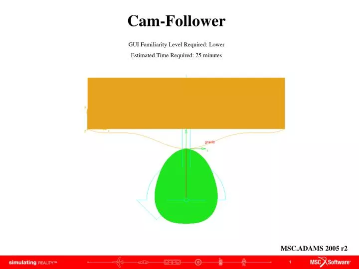
Cam-FollowerGUI Familiarity Level Required: Lower Estimated Time Required: 25 minutes MSC.ADAMS 2005 r2
Topics Covered In this tutorial you will learn how to: • How to manipulate the grid spacing • How to create different shapes using the open and closed splines • How to add constraints (joints): revolute joint, translational joint and a 2D curve-curve constraint • How to create a rigid body: box • How to measure • How to run simulations • How to plot • How to save If you have any difficulties, import the “cam_follower_shortcut_1.cmd” file and proceed from pg 10 If you have any difficulties, import the “cam_follower_shortcut_2.cmd” file and proceed from pg 13 If you have any difficulties, import the “cam_follower_complete.cmd” file and proceed from pg 18
Cam-Follower Problem The cam mechanism that will be created, analyzed, animated, and plotted in this lab is shown here. Schematic of the Cam Mechanism: The model contains 3 parts (including ground), 1 revolute joint, 1 translational joint, 1 motion, and several markers.
What You Should Accomplish If you are successful you should end up with a working ADAMS model that illustrates the movement of a follower along the cam’s contour.
Create New Model Getting Started: a. Under the heading "How would you like to proceed", select the Create a new model radio button. b. Choose a Location to save your files c. Choose model_1 as Model Name d. Verify the Gravity text field is set to Earth Normal (-Global Y). e. Verify that the Units text field is set to MMKS - mm,kg,N,s,deg. f. Select OK. a b c d e f
Settings • To edit the grid size: • Click Settings menu, then Working Grid… • The Working Grid Settings window will appear • Change the Spacing text fields in X and Y to (10mm) • Click OK a b c
Closed Body Spline Creating an Closed Spline: Cam • a. Right-click on the tool stack, click on Spline • Select New Part from Spline pull down menu • Turn on checkbox next to Closed. • Click on the 13 points in the table below. • Right click on the cam to create a closed spline • *Note that the first point and the last point have the same coordinates to create a closed spline. b a c d
Closed Body Spline • a. An alert box will appear warning you that the part has no mass. Close the box. • The complete cam part is created DOWNLOAD FILE • *If your part's geometry does not match the illustration, it can be fixed by clicking and dragging any of the "hot points" (rectangular boxes) to its proper location a
Create Revolute Joint • Click Joint tool stack, select Joint: Revolute • Verify that the Construction text fields read 2 Bod-1 Loc. • Left-click on any blank area in the working window (ground) • Left click on your cam • Click on the position (0,-130,0)A joint between the cam part and the ground is created at that location a c d b e
Open Body Spline • Select the Spline tool • Turn on checkbox next to Closed. • Click on the 28 points in the table below. • Right click to create a closed spline • *Note that the first point and the last point have the same coordinates to create a closed spline. a b c *Note: To View into Excel, Right click on table, go to Worksheet Object > Open
Open Body Spline a. An alert box will appear warning you that the part has no volume. Close the box. The complete part is created DOWNLOAD FILE *If your part's geometry does not match the illustration, it can be fixed by clicking and dragging any of the "hot points" (rectangular boxes) to its proper location
Create Box • Select the Box tool from the Rigid body tool stack. • Select Add to Part from Box pull down menu • Click on the spline in the ADAMS window to select the part to add to. • Now define the corners of the box. • Click on the left end of the open spline (-250,50,0). • Click on (250,180,0). e a d b c
Create Cylindrical Joint • Now create a cylindricall joint between the follower part and the ground part with the axis of translation aligned in the global y direction. • Select the Joint:Cylindrical tool from the Joint tool stack. • Verify that the Construction text fields are set to 1 Location and Pick Feature. • Click on PART_3.cm • Move the cursor in the positive Global Y axis until an arrow pointing straight up appears. Click once. Make sure the arrow is parallel to the Y axis. This arrow determines the direction of the translational joint. c d a b
Create Curve-on-Curve Contact • Select the Cam (curve-on-curve) contact tool from the Joints button stack. • Click on the cam part • Click on the follower c a b
Add Rotational Joint Motion • Add a rotational motion driver to the revolute joint that specifies a constant cam rotation of one revolution per second. • Select the Rotational Joint Motion icon from the motion toolbox. • In the Speed text field, enter (360d) to set the motion displacement to be 360 degrees/second. • Left-click on the revolute joint (JOINT_1). a b c
Verify • Right-Click on the Information Icon in the bottom right corner of the Working Window • Left-click on the Verification Icon a b c. After seeing that the model has verified successfully, click on the Close button. c
Model This is what your screen should look like when your model is complete
Measure • Right click the follower part and choose measure. • The Part Measure dialog box appears. • Select CM Position from Characteristic pull down menu and select Y for the Component entry to measure the displacement in the Y direction. • Click Apply. • A graph window appears. This is where data will be displayed. • Repeat, step b & c, except use CM Velocity for Characteristic. • Repeat, step b & c, except use CM Acceleration forCharacteristic.A new graph window will appear for each new measure. • After the three graph windows are created, click Cancel to close the Part Measure dialog box b a c f
Simulation • Click on the Simulation tool in the Toolbox. • Enter 1 in End Time text field • Change Steps to Step Size, enter .01 in the text field • Click on the Play icon. You should see the cam rotate about the pivot and the follower slide along its translational joint.Corresponding data should be plotted on each graph. • When the simulation ends, click on the Rewind icon. a e d b c
Plotting • In each of the graph windows, a plot corresponding to each of the measures set earlier appears. • To get a closer look at a plot, click on a blank area inside the small plot window with the right mouse button and follow the pull right menu. Select Transfer to Full Plot. b c. The ADAMS Plot Window will open, replacing the modeling window. To return to the modeling window, go to the File pull-down menu and select Close Plot Window or press F8 or click on the Return to modeling environment button c
Viewing Plots • To view other plots: • Select Objects for the source text field • Choose a Filter (Body, Force. Constraint) • Choose an Object • Choose a Characteristic • Choose a Component • Select Surf if you would like to replace the curve in the Plot Window, or select Add Curves to add more curves to the window f b c d e a
Saving • Return to ADAMS modeling window • Under the File pull-down menu, select Save Database As… a • The Save Database As dialog box appears • In the text field next to File Name, enter the name you wish to give this model, for example, cam. • Select OK. b c A binary file (.bin) has been created in the folder you choose when opening ADAMS
Topics Covered In this tutorial, you learned how to: • manipulate the grid spacing • create different shapes using the open and closed splines • add constraints (joints): revolute joint, translational joint and a 2D curve-curve constraint • create a rigid body: box • measure • run simulations • plot • save
Best Practices • Make sure correct units are set to mmks. • Make sure the revolute joint is in the z direction. • Make sure Cylindrical joint is in the y direction. • Check dimensions of the part to make sure they are correct. • Check locations of spline points to make sure they are correct. • Check orientation of the parts to make sure they are correct. • Verify your model. • Make sure the measures are set correctly. • Make sure the plot is displaying the correct set of results
Further Analysis (Optional) Is there any other way to create a cam follower system? Change the cam or follower geometry and see how this will effect the simulations What happens if you move the “hot point” (0,-190,0) on the cam to (0,-180,0) What happens if you move the “hot point” (0,-190,0) on the cam to (0,-230,0)