Download
1 / 54
540 likes | 549 Views
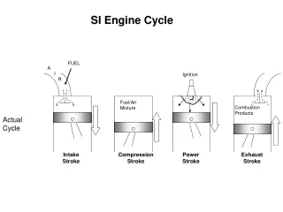
In-Cylinder Process in SI Engine. P M V Subbarao Professor Mechanical Engineering Department. Air Fuel Mixture is Ready for Anything Possible…. Compression of Fuel – Air Mixture in SI Engine. Air+Fuel vapour + fuel droplets +Residual gas. Compression Process. P.

E N D
In-Cylinder Process in SI Engine P M V Subbarao Professor Mechanical Engineering Department Air Fuel Mixture is Ready for Anything Possible….
Compression of Fuel – Air Mixture in SI Engine Air+Fuel vapour + fuel droplets +Residual gas Compression Process
P Representing wet compression process on P-V diagram W isothermal = f-1-2T-g-f (isothermal) W wet compression = f-1-2K-g-f (wet compression) W isentropic = f-1-2S-g-f (isentropic) W polytropic = f-1-2n-g-f (polytropic) P 2T 2k 2s 2n g 2 f 1 P 1 0 V
ISENTROPIC INDEX OF WET COMPRESSION PROCESS • Isentropic index of wet compression can be obtained from the equation Where K=Isentropic index of wet compression, dw/dT = Evaporative rate kg/k, L= Latent heat kj/kg, R=Gas constant of humid air kj/kg k.
ACTUAL WET COMPRESSION INDEX • Actual wet compression index can be obtained from the equation Where m=polytropic index of actual wet compression process, n=polytropic index of actual dry air compression
Phenomenological Understanding: Ignition to Combustion End of Combustion Start of Combustion Initiation of Ignition Crank Angle,q
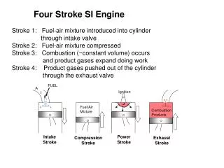
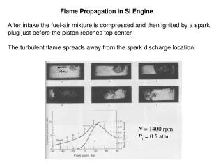
Combustion in SI Engines • The term combustion is saved for those exothermic reactions that take place very rapidly with large conversion of chemical energy into sensible energy. • Onset of such rapid exothermal reaction can occur only when the eligible fuel-air mixture reaches its self-ignition temperature. • Low atomicity fuels demand an artificial means, called Spark, to create this situation. • When a combustible fuel-air mixture is ignited with a spark, a flame propagates with a velocity determined by the kind of fuel-air mixture and the external conditions.
The pace of Flame Travel • Accordingly; the velocity of flame propagation depends on whether; • the vessel is taken as a reference or • the unburned gas is taken as reference. • Usually, the former is referred to as the flame travel speed. • The latter is known as the flame propagation speed or the flame velocity.
Add Wisdom to The Listening In above Eq., the rate of the heat loss dQloss/dθ is expressed as: The convective heat transfer coefficient is given by the Woschni model as For combustion and expansion processes: C1=0.00324.
Phenomenological Understanding: Ignition to Combustion End of Combustion Start of Combustion Initiation of Ignition Crank Angle,q
Ignition Systems • The job of an ignition system is to create an environment, which can help few fuel molecules to reach their self ignition temperature. • Simply saying pouring of few ions into cylinder!!! • This will self ignite the air/fuel mixture in an engine's cylinder. • The main components of this system consist of an ignition coil, coil driver, distributor, spark plug wires, and spark plugs. • Types of Ignition Systems: • Magnetos • Kettering Ignition • Electronic Ignition • Inductive Discharge vs Capacitive Discharge Ignition (CD)
Physics of Sparking • In 1889, F. Pashchen published a paper which set out what has become known as Paschen's Law. • The law essentially states that, at higher pressures (above a few torr) the breakdown characteristics of a gap are a function (generally not linear) of the product of the gas pressure and the gap length. • Usually written as V= f( pd ), where p is the pressure and d is the gap distance. • Extensive additional experiments for different materials, lower pressures, different gases and a variety of electrode shapes have expanded the data set involved.
Spark Ignition • The electrical discharge produced between spark plug electrodes starts the combustion process • A high-temperature plasma kernel created by the spark develops into a self-sustaining and propagating flame front • A spark is caused by applying a sufficiently high voltage between two electrodes separated by explosive gas in the gap. • When the spark energy is increased, that is, when the voltage across the electrodes is raised above a certain critical value (below which a spark may not even occur), a threshold energy is eventually obtained at which the spark ignites the charge • This minimum ignition energy is a function of properties of the explosive gas and the configuration of the spark gap.
Breakdown Voltage vs. Pressure • Paschen's Law states that the critical voltage (at which spark would occur) is a function of the product of the dimensions of the gap and the gas pressure. • The manner in which voltage is raised to the critical value; • configuration and condition of the electrodes and • the nature of the combustible mixture are all important in relation to the energy required.
Paschen Curve Paschen found that breakdown voltage was described by the equation Where V is the breakdown voltage, p is the pressure, d is the gap distance. The constants a and b depend upon the composition of the gas. For air at standard atmospheric pressure of 101 kPa, a = 43.6×10⁶ V/(atm·m) and b = 12.8.
Ignition Systems • The job of an ignition system is to create an environment, which can help few fuel molecules to reach their self ignition temperature. • Simply saying pouring of few ions into cylinder!!! • This will self ignite the air/fuel mixture in an engine's cylinder. • Types of Spark Ignition Systems: • Magnetos • Kettering Ignition • Electronic Ignition • Inductive Discharge vs Capacitive Discharge Ignition (CD)
Spark Ignition • A spark is caused by applying a sufficiently high voltage between two electrodes separated by explosive gas in the gap. • When the the voltage across the electrodes is raised above a certain critical value (below which a spark may not even occur), a threshold energy is eventually obtained at which the spark ignites the charge • This minimum ignition energy is a function of properties of the explosive gas and the configuration of the spark gap. • The electrical discharge produced between spark plug electrodes starts the combustion process • A high-temperature plasma kernel created by the spark develops into a self-sustaining and propagating flame front
Paschen Curve Paschen found that breakdown voltage was described by the equation Where V is the breakdown voltage, p is the pressure, d is the gap distance. The constants a and b depend upon the composition of the gas. For air at standard atmospheric pressure of 101 kPa, a = 43.6×10⁶ V/(atm·m) and b = 12.8.
One curve corresponds to a series of experiments in which the electrode terminals were tipped with stainless steel spheres of 1.5 mm diameter. In the other series, the electrodes were similarly tipped and in addition were flanged by glass plates.
Evolution of Baby Spark into Baby Flame (Flamelet)ignition of the mixture
Ignition energy in air at 1 atm, 20C Fuel E’ (10-5J) Methane 33 Ethane 42 Propane 40 n-Hexane 95 Iso-Octane 29 Acetylene 3 Hydrogen 2 Methanol 21
Minimum Spark Energy • The minimum energy required to ignite a air-fuel mixture . • Effect of Various Parameters on MIE: • Distance Between Electrodes • Fuel • Equivalence Ratio • Initial Temperature • Air Movement • Any situation leading to unavailability of required MSE will create missing stroke/incomplete combustion stroke. • This will reduce the fuel economy of SI engines.
Effect of velocity on spark ignition Remark: when the mixture is moving ignition is more difficult Geometrical Model for Kernel due to spark ignition in flow.
Other Ignition systems • Ignition by an electrically heated wire • Ignition by flame or hot jet • Plasma jet ignition • Photochemical ignition • Microwave ignition • Laser ignition • Puff-jet ignition February 21, 2015: Laser ignition demonstrated in a real engine could boost engine efficiency by 27%. http://nextbigfuture.com/2015/02/laser-ignition-demonstrated-in-real.html
Onset of A Successful Combustion in Homogeneous Charge • A successful spark creates a shock wave in the air-fuel mixture. • This shock wave expands against air fuel mixture. • A photographic study of the phenomena controlling the initial behaviour of spark-ignited flames confirmed that combustion starts as self-ignition. • This self ignition occurs in the volume of very hot gases (kernel) behind the shock wave. • Spark-ignited flames pass through a non-steady propagation period before reaching a steady speed. • This transient period is relatively important, compared to the total time available for combustion, in an engine cycle.
Phases in Flame Development Flame development angleDqd – crank angle interval during which flame kernal develops after spark ignition. Rapid burning angleDqb – crank angle required to burn most of mixture Overall burning angle - sum of flame development and rapid burning angles Mass % of burned Fuel CA
Mixture Burn Time B Scomb : Flame velocity If we take a typical value of 50o crank angle for the overall burn N (rpm) t90%(ms) Scomb,req (m/s) Standard car at idle 500 16.7 3.0 Standard car at max power 4,000 2.1 23.8 Formula car at max power 19,000 0.4 125
Empirical Correlations to Select Combustion Parameters T in K & p in atm.
Mixture Burn Time B If we take a typical value of 50o crank angle for the overall burn N (rpm) t90%(ms) Scomb,req (m/s) Standard car at idle 500 16.7 3.0 Standard car at max power 4,000 2.1 23.8 Formula car at max power 19,000 0.4 125 How is Otto’s Engine Ran at higher Speed????
Mercedes 35 PS : 1901 Sein vorne angeordneter Vierzylinder-Reihenmotor ist direkt mit dem erstmals aus Stahlblech gepressten Rahmen verschraubt und leistet sensationelle 35 PS. Die Drehzahlregelung zwischen 300/min und 1000/min erfolgt über einen Hebel am Lenkrad. Zylinder und Zylinderkopf bilden eine Einheit, das Kurbelgehäuse besteht erstmals aus Aluminium. Its four-cylinder row engine arranged in front is bolted direct with the framework pressed for the first time from steel sheet and carries sensational 35 HP out. Speed regulation between 300/min and 1000/min is made by a lever at the steering wheel. Cylinders and cylinder head form a unit, the crank case consist for the first time of aluminum.
Need for Turbulent Flow • High speed engines are possible only due to turbulent combustion. • The turbulent flow field in an engine plays important role in determining its combustion characteristics and thermal efficiency. • Automotive engineers have learned that changes in the combustion chamber shape and inlet system geometry, both of which change the turbulent flow field, influence emissions, fuel economy and the lean operating limit of an engine. • Most of this knowledge has been obtained on specific engines through direct experimentation or from global measurements. • There exists no general scaling laws to predict the combustion and emission characteristics of an engine.
Evidence of Organized Structure in an Engine1200 rpm motored engine 90 Cycle Mean Velocity Distribution In Mid- Plane Instantaneous Velocity Distribution In Mid Plane During Cycle 20 Instantaneous Velocity Distribution In Mid Plane During Cycle 1
Creative Ideas to Generate Turbulent Flow : Swirl based systems
Creative Ideas to Generate Turbulent Flow : Squish based GDI concepts