Download
1 / 1
10 likes | 116 Views
N U users are drawn from a uniform distribution on a 15 x 20 grid. Path loss : with , and , and nominal SNR: 16.8~19.1dB (at cell edges), 43.1dB (at cell centers) Log-normal shadowing with zero mean and a shadowing standard deviation dB.

E N D
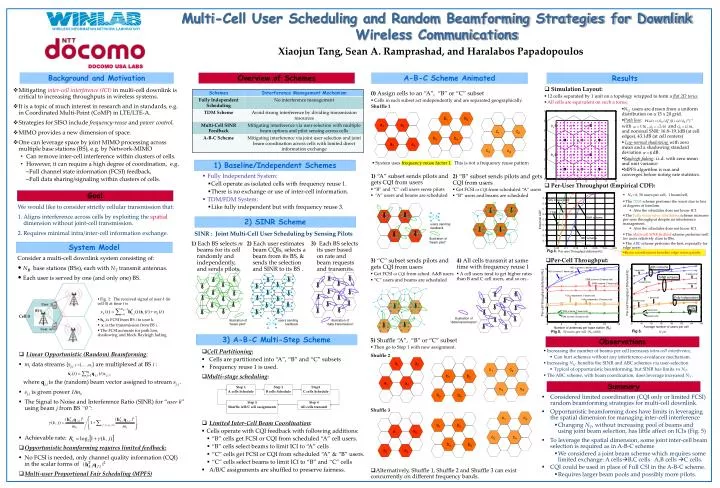
NU users are drawn from a uniform distribution on a 15 x 20 grid. • Path loss: with , and , and nominal SNR: 16.8~19.1dB (at cell edges), 43.1dB (at cell centers) • Log-normal shadowingwith zero mean and a shadowing standard deviation dB. • Rayleigh fading: i.i.d. with zero mean and unit variance • MPFS algorithm is run and converges before noting rate statistics. b1 b2 c1 c2 b3 b4 c3 c4 c1 c2 b1 a1 b2 a2 c3 c4 a3 b3 a4 b4 Multi-Cell User Scheduling and Random Beamforming Strategies for Downlink Wireless Communications Xiaojun Tang, Sean A. Ramprashad, and Haralabos Papadopoulos DOCOMO USA LABS Background and Motivation Overview of Schemes A-B-C Scheme Animated Results • Simulation Layout: • 12 cells separated by 1 unit on a topology wrapped to form a flat 2D torus. • All cells are equivalent on such a torus. • Mitigating inter-cell interference (ICI)in multi-cell downlink is critical to increasing throughputs in wireless systems. • It is a topic of much interest in research and in standards, e.g. in Coordinated Multi-Point (CoMP) in LTE/LTE-A. • Strategies for SISO include frequency-reuse and power control. • MIMO provides a new dimension of space. • One can leverage space by joint MIMO processing across multiple base stations (BS), e.g. by Network-MIMO • Can remove inter-cell interference within clusters of cells. • However, it can require a high degree of coordination, e.g. • Full channel state information (FCSI) feedback, • Full data sharing/signaling within clusters of cells. 0) Assign cells to an “A”, “B” or “C” subset • Cells in each subset act independently and are separated geographically. Shuffle 1 a1 a2 a3 a4 • System uses frequency reuse factor 1. This is not a frequency reuse pattern. 1) Baseline/Independent Schemes • Fully Independent System: • Cell operate as isolated cells with frequency reuse 1. • There is no exchange or use of inter-cell information. • TDM/FDM System: • Like fully independent but with frequency reuse 3. 1) “A” subset sends pilots and gets CQI from users • “B” and “C” cell users sense pilots • “A” users and beams are scheduled 2) “B” subset sends pilots and gets CQI from users • Get FCSI or CQI from scheduled “A” users • “B” users and beams are scheduled • Per-User Throughput (Empirical CDF): Goal • NT = 6, 50 users per cell, 1 beam/cell, • The TDMscheme performs the worst due to loss of degrees of freedom. • Also the scheduler does not know ICI. • The Fully independent scheduling scheme increases per-user throughput despite no interference management. • Also the scheduler does not know ICI. • The Multi-cell SINR feedback scheme performs well for users relatively close to BSs. • The ABC schemeperforms the best, especially for edge users. • Beam coordination benefits edge users greatly. Step 1 A cells Schedule Step 2 B cells Schedule Step3 C cells Schedule We would like to consider strictly cellular transmission that: Aligns interference across cells by exploiting the spatial dimension without joint-cell transmission. Requires minimal intra/inter-cell information exchange. User 1 Step 5 Shuffle A/B/C cell assignments Step 4 All cells transmit 2) SINR Scheme BS 0 users sending feedback Cell 0 SINR : Joint Multi-Cell User Scheduling by Sensing Pilots User m illustration of “beam pilot” 1) Each BS selects m beams for its cell randomly and independently, and sends pilots. 2) Each user estimates beam CQIs, selects a beam from its BS, & sends the selection and SINR to its BS . 3) Each BS selects its user based on rate and beam requests and transmits. System Model Fig 4. Consider a multi-cell downlink system consisting of: • NB base stations (BSs), each with NT transmit antennas. • Each user is served by one (and only one) BS. • Per-Cell Throughput: 4) All cells transmit at same time with frequency reuse 1 • A cell users tend to get higher rates than B and C cell users, and so on... 3) “C” subset sends pilots and gets CQI from users • Get FCSI or CQI from sched. A&B users • “C” users and beams are scheduled • Fig. 1: The received signal of user k (in cell 0) at time t is • hk,i is FCSI from BS i to user k • xi is the transmission from BS i. • The FCSI accounts for path loss, shadowing and block Rayleigh fading. illustration of “data transmission” illustration of “beam pilot” users sending feedback illustration of “data transmission” Fig 6. Fig 5. 50 users per cell (NU=600) NT=6 3) A-B-C Multi-Step Scheme Observations 5) Shuffle “A”, “B” or “C” subset • Then go to Step 1 with new assignment. Shuffle 2 Shuffle 3 • Alternatively, Shuffle 1, Shuffle 2 and Shuffle 3 can exist concurrently on different frequency bands. • Cell Partitioning: • Cells are partitioned into “A”, “B” and “C” subsets • Frequency reuse 1 is used. • Multi-stage scheduling: • Limited Inter-Cell Beam Coordination: • Cells operate with CQI feedback with following additions: • “B” cells get FCSI or CQI from scheduled “A” cell users. • “B” cells select beams to limit ICI to “A” cells • “C” cells get FCSI or CQI from scheduled “A” & “B” users. • “C” cells select beams to limit ICI to “B” and “C” cells • A/B/C assignments are shuffled to preserve fairness. • Increasing the number of beams per cell increases intra-cell interference, • Can hurt schemes without any interference-avoidance mechanism. • Increasing NU benefits the SINR and ABC schemes via user-selection • Typical of opportunistic beamforming, but SINR has limits vs NT. • The ABC scheme, with beam coordination, does leverage increased NT. • Linear Opportunistic (Random) Beamforming: • mi data streams {sj,ij =1,…,mi} are multiplexed at BS i : where qj,iis the (random) beam vector assigned to stream sj,i . • sj,i is given power 1/mi, • The Signal to Noise and Interference Ratio (SINR) for “user k” using beam j from BS “0”: • Achievable rate: • Opportunistic beamforming requires limited feedback: • No FCSI is needed, only channel quality information (CQI) in the scalar forms of . • Multi-user Proportional Fair Scheduling (MPFS) a1 a2 a3 a4 Summary • Considered limited coordination (CQI only or limited FCSI) random beamforming strategies for multi-cell downlink. • Opportunistic beamforming does have limits in leveraging the spatial dimension for managing inter-cell interference • Changing NT, without increasing pool of beams and using joint beam selection, has little affect on ICIs (Fig. 5) • To leverage the spatial dimension, some joint inter-cell beam selection is required as in A-B-C scheme • We considered a joint beam scheme which requires some limited exchange: A cellsB,C cells A,B cells C cells. • CQI could be used in place of Full CSI in the A-B-C scheme. • Requires larger beam pools and possibly more pilots. c1 c2 b1 b2 c3 c4 b3 b4