Download
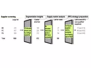
1 / 38
520 likes | 905 Views
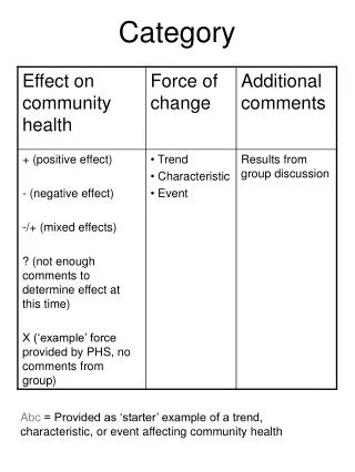
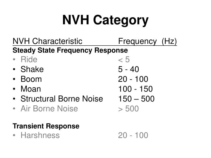
NVH Category. NVH Characteristic Frequency (Hz) Steady State Frequency Response Ride < 5 Shake 5 - 40 Boom 20 - 100 Moan 100 - 150 Structural Borne Noise 150 – 500 Air Borne Noise > 500 Transient Response Harshness 20 - 100. Control by Damping. Control by Dynamic

E N D
NVH Category NVH Characteristic Frequency (Hz) Steady State Frequency Response • Ride < 5 • Shake 5 - 40 • Boom 20 - 100 • Moan 100 - 150 • Structural Borne Noise 150 – 500 • Air Borne Noise > 500 Transient Response • Harshness 20 - 100
Control by Damping Control by Dynamic Stiffness Control by Mass Isolation Region fn * fn Single Degree of Freedom
Dynamic Stiffness Dynamic Stiffness: (K - m ω2) – j C ω K* = ---------------------------------- (K - m ω2)2 + (C ω)2 ω = 2* π*f f is the frequency Mass M Stiffness K Damping C
Pure Tone • Sound at a single frequency • Sound Pressure • Objective measurement • dB • Logarithmic of sound pressure • dBA • A-Weighted to adjust for ear sensitivity
Human Sensitivity • More constant across frequency range with velocity • Hearing range 20 – 2000 Hz • Depends on overall level • Sound at one frequency may mask by other frequencies • Depends on age, sex and other factors
Acceleration SR = 5 SR = 6 Frequency Tactile ResponseSubjective-Objective
Velocity SR = 5 SR = 6 Frequency Tactile ResponseSubjective-Objective (2)
NVH Classification • Operating Condition • Idle, Low Speed, Cruising, POT, WOT • Subjective Evaluation • Shake, Boom, Noise, Harshness • Objective Measurement • Sound Pressure, Acceleration • Frequency Range • Source • Powertrain, Road, Exhaust
NVH Subjective Rating Most Targets No Sale
NVH Objectives • Assess vehicle responses relative to design targets: • Tactile responses • Seat track • Steering column • Toe pan • Acoustic responses • Driver’s ear • Front Passenger’s ear • Rear passenger’s ear
Shake • 5 – 40 Hz • Idle Shake • Isolated Road Shake • Rough Road Shake • Smooth Road Shake • Wheel/Tire Imbalance • Tire Force Variation
Design For Shake • Body vertical, lateral bending and torsion modes • Front end bending and torsion modes • Front floor modes • Steering column modes • Seat modes • Avoid stickiness of the shock and CV joints that causes high force input and resonance in smooth road shake
Design For Shake (2) • Mode separation and mode shape management of engine bounce, roll, pitch and yaw rigid body modes
Boom • 20 - 100 Hz • Idle Boom • Isolated Road Boom • Rough Road Boom
Body Design for Boom • 1st and 2nd fore-aft acoustic modes • Body 1st and 2nd order vertical bending • Front floor vertical bending • Dash panel fore-aft bending • Quarter panel bending • Fuel tank bounce • Spare tire tub bounce • Decklid, liftgate or lower back panel pumping
Structural Borne Noise • 100 - 500 Hz • Powertrain Noise • Rough Road Noise • Gear Whine
Design For Noise • Most of the vibration energy imparted to the vehicle is below 150 Hz. • Below 150 Hz: • Body structure is important for controlling noise and vibration • Lack of structure usually results in costly design and tooling changes • Above 150 Hz: • Can be resolved with relatively simple structure modifications, such as bead patterns, or damping treatments.
Design For Noise (2) • Powertrain Bending Isolation • Powertrain Bracket Isolation
Modal Chart CHASSIS/POWERTRAIN MODES Suspension Hop and Tramp Modes Ride Modes Suspension Longitudinal Modes Powertrain Modes Exhaust Modes 0 5 10 15 20 25 30 35 40 45 50 Hz BODY/ACOUSTIC MODES Body First Torsion (25Hz) Steering Column First Vertical Bending (29Hz) Body First Bending (22Hz) First F/A Acoustic Modes (48Hz) 0 5 10 15 20 25 30 35 40 45 50 Hz EXCITATION SOURCES Inherent Excitations (General Road Spectrum, Reciprocating Unbalance, Gas Torque, etc.) Process Variation Excitations (Engine, Driveline, Accessory, Wheel/Tire Unbalances) V8 Idle (500-550RPM) Hot Cold First Order Wheel/Tire Unbalance (5-75MPH) 0 5 10 15 20 25 30 35 40 45 50 Hz
Body-in-White Targets • Static Stiffness • Bending • Torsion • Normal Modes • Vertical bending • Torsion • Lateral bending
Trimmed Body Targets • Normal Modes • Vertical bending • Torsion • Lateral bending • Front end bending • Front end torsion
Instrument Panel/Column Targets • Normal Modes • Vertical bending • Lateral bending
Seat Targets • Normal Modes • On Bedplate • Fore aft • Lateral • In Vehicle • Fore aft • Lateral • Different row may have different target
Pbore mrecip arecip h L r Pcrank Idle Torque
Pbore mrecip arecip h L r Pcrank Piston Displacement
Pbore mrecip recip h L r Pcrank Trigonometric Derivatives
Pbore mrecip arecip h L r Pcrank Piston Velocity
Pbore mrecip arecip h L r Pcrank Piston Acceleration
Wheel/Tire Imbalance Definition • Simulation • Shake caused by the unbalanced inertia forces from the high speed rotation of the unbalanced wheel in vehicle cruising • Load • 1.0 oz-inch (Sensitivity) unbalanced force at the spindles • Both vertical and fore-aft loads with vertical load trailing fore-aft load by 90 degrees • Applications • Front wheel in-phase, Front wheel out-of-phase, Rear wheel in-phase and Rear wheel out-of-phase
Wheel/Tire Imbalance Calculation • F = mr2 • F is imbalance Force (N) • m is imbalance mass (Mg) • r is imbalance radius (mm) • is rotation speed (rad/sec) • F = 1.0 oz-in = 1.0 * 28.3 * 10-6 (Mg/oz) * 25.4 (mm/inch) * 4 * 2 * f2 = 0.0284 * f2 (N) • f is frequency (cycles/sec)
Wheel/Tire ImbalanceSpeed Map • The wheel/tire speed map (frequency v.s. vehicle speed) is dependent on the wheel/tire size, the wheel/tire stiffness and the payload • V = 2 * π * Tire Effective Radius * Frequency • However, the Frequency/Vehicle Speed(MPH) is typically around 0.2 • Based on the above assumption, the frequency range of interest from 25 MPH to 125 MPH is • 5 Hz to 25 Hz
Tire Force Variation Definition • Simulation • Shake caused by the variation of the radial stiffness of the tires • Load • 1.0 lbf (Sensitivity) variation force at the spindles • Vertical load only • Applications • Front wheel in-phase, Front wheel out-of-phase, Rear wheel in-phase and Rear wheel out-of-phase
Tire Force VariationSpeed Map • The wheel/tire speed map (frequency v.s. vehicle speed) is dependent on the wheel/tire size, the wheel/tire stiffness and the payload • V = 2 * π * Tire Effective Radius * Frequency • However, the Frequency/Vehicle Speed(MPH) is typically around 0.2 • Based on the above assumption, the frequency ranges of interest from 25 MPH to 125 MPH are • First Order : 5 Hz to 25 Hz • Second Order : 10 Hz to 50 Hz
Spatial PSD Road Profile • Spatial Frequency ( Cycles / mm) • Wave number • 1 / wavelength • PSD Amplitude (mm^2 / (cycles / mm)) • Power Regression Analysis (Y = 1.7872 * X-0.6729)