Download
1 / 11
120 likes | 238 Views
NSLS-II Frontends and Canted Wigglers Options. Sushil Sharma. BM Photon Shutter. Bremsstrahlung Stop. ID Frontend. ID Beamline. BM Beamline. Slow Gate valve. BM Frontend. Schematic Layout of a Cell. ID and BM Frontends. Beam. Configuration without a Frontend. Exit Port. Lead

E N D
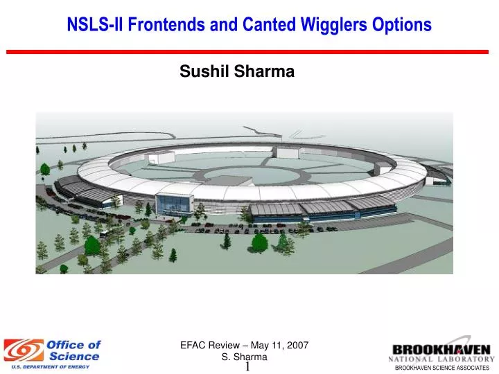
NSLS-II Frontends and Canted Wigglers Options Sushil Sharma
BM Photon Shutter Bremsstrahlung Stop ID Frontend ID Beamline BM Beamline Slow Gate valve BM Frontend Schematic Layout of a Cell ID and BM Frontends Beam Configuration without a Frontend Exit Port
Lead Collimator Fast Gate Valve Safety Shutter Fixed Mask Slow Gate Valve XBPM1 XBPM2 Photon Shutter Typical NSLS-II Frontend BM Photon Shutter • Only one fixed mask and one photon shutter are used in a frontend. • The BM photon shutter before the slow gate valve eliminates the need for another slow gate valve in the frontend.
Frontend Components Lead Collimator Photon shutter APS fixed mask design XBPM Safety shutters
Front end – Thermal Analysis Glidcop 7.4 m 0.5 m For the front-end components the calculated temperature is ~ 430 ºC a thermal fatigue life of greater than 10,000 cycles.
Canted Wigglers Option 10.3 m Dipole Chamber - 1 Typical Chamber Cross-Section
Crotch Absorber Wiggler Absorber Chamber 2 Chamber 3 Canted Wigglers Option – contd. Crotch Absorber Wiggler Absorber • Bellows assemblies are required to accommodate thermal expansions of the chambers during bakeout and misalignment of the flanges. • Two bellows assemblies (inboard and outboard) are preferable considering beam impedance, cost and schedule. • Hardware or “crotch” between the two bellows assemblies must be protected by a crotch absorber.
4 mrad 6 mrad Canted Wigglers Option – contd. Fans of New Canted Wigglers at 10 m • The wiggler(s) fan is limited to ~ 6 mrad, which is trimmed to ~ 4 mrad by the wiggler absorber, in order to get the fan out to the frontend. A significantly larger fan will require extensive modifications of the chambers, absorbers and magnets. • The new wigglers with a fan of ± 2.3 mrad can be canted to ~ 2 mrad.
SR Absorbers – Thermal Analyses Wiggler Absorber Crotch Absorber • The crotch absorber intercepts 814 W at a normal peak power density of 0.25kW/mm2. A maximum temperature of 105 ºC is calculated. • The total intercepted power by the wiggler absorber is 11 kW out of 65 kW. This results in a maximum temperature of 427 ºC. A fatigue life of > 10,000 cycles is expected.
Magnet Modifications for Exit ports Wiggler Absorber Exit Port APS Exit Port NSLS-II Wiggler Exit Port
Summary: • Preliminary design and analysis of the ID, wiggler and BM frontends are in progress. • Wiggler(s) radiation fan must be limited to approximately ± 3 mrad in order to use the standard aluminum extrusions, absorbers, exit ports and associated magnets. • Wigglers with a fan of approximately ± 2.3 mrad fan can be canted to ~ 2 mrad.