Download
1 / 21
220 likes | 383 Views
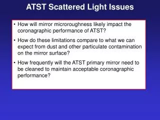
AN ALIGNMENT STRATEGY FOR THE ATST M2 Implementing a standalone correction strategy for ATST M2. Robert S. Upton NIO/AURA February 11,2005. BACKGROUND. NSO hired ORA to perform a sensitivity analysis of the ATST Optical performance is most sensitive to M2 misalignments

E N D
AN ALIGNMENT STRATEGY FOR THE ATST M2 Implementing a standalone correction strategy for ATST M2 Robert S. Upton NIO/AURA February 11,2005
BACKGROUND • NSO hired ORA to perform a sensitivity analysis of the ATST • Optical performance is most sensitive to M2 misalignments • Image and pupil boresight error correctible with M3 and M6 tilts • ORA have defined an alignment strategy using their AUT optimization routine in CODE V • NSO would like a “standalone” reconstruction/optimization control strategy that can restore optical performance subject to M2
OUTLINE • Statement of work • Analysis • a. Pupil and image boresight • b. Zernike coefficients • c. Linear mathematical analysis. • 3. Correction strategy • 4. Summary • 5. Other thoughts
STATEMENT OF WORK • Develop an understanding of the problem • Develop a suitable optical model • Perform analysis to develop suitable alignment strategy • Test the strategy • Comment of potential future areas of analysis and development
ATST OPTICAL MODEL • Use CODE V macro capability to perturb ATST, develop boresight relations, Zernike sensitivity analysis, and test correction strategy
ANALYSIS • Characterize the pupil and image bore sight sensitivities • Characterize the higher-order optical sensitivities M2 • Determine ATST system linearity • ATST linear analysis • Alignment strategy. Linear reconstruction and optimization
M3 AND M6 MOTION SENSITIVITY ANALYSIS: Maintaining pupil and image boresight • Determine the angular motions of M3 and M6 that maintain pupil and image alignment subject to changing M2 • Used CODE V optimizer with gut ray position constraint • Determined that and rotation are most sensitive for M3 and M6 • Second-order angular contributions and cross-term contributions have significance c subscript denotes compensator motions
PREALIGNMENT TEST • Apply boresight equations to actual perturbation test • Data arranged to provide all combinations of decenters and tilts, except rotation about Z X X … X X Z Z Z Z Y Y
DEFINE THE PRE-ALIGNMENT CORRECTIONPupil and Image motion • Perturb the telescope by a total of 400 m in decenters and 0.4 degrees in tilts
(0, 1.5 arc-min) Perturb telescope Perform pre-alignment Determine Zernike coefficient (-1.5 arc-min, 0) (1.5 arc-min, 0) Renew telescope prescription HIGHER-ORDER OPTICAL SENSITIVITY FOR M2 • Perturb the M2 through its 6 DOF and calculate the resulting Zernike (rms) coefficients at three field locations • The rms Zernike coefficients Z4, Z5, Z6, Z7, Z8, Z9, and Z10 are calculated • These Zernike coefficients quantify astigmatism, focus, trefoil and coma • M2 is decentered through 20 values from 0 to 2 mm • M2 is decentered through values from 0 to 0.2 degrees • The Zernike coefficient sensitivities are determined whilst correcting the boresight error
HIGHER-ORDER OPTICAL SENSITIVITY FOR M2 • The Zernike coefficients are fit to a second-order vector polynomial resulting in matrix coefficients C0, C1, C2 • Linear algebraic analysis is performed on the linear matrix coefficient C1. Determines linear independence • M2 reconstruction is demonstrated in the linear limit
? DETERMINE ATST SYSTEM LINEARITY • ATST system linearity is encapsulated in C1 • If system is largely linear then a large range of elegant linear algebraic tools can be used to restore optical performance for the perturbed ATST • In other words, WFS Modes
ATST SYSTEM LINEARITY Z4(y) Z4() Z5(y) Z5(z) Z5() Z6(x) Z6() • Most dominant aberrations and DOF are linear
ATST LINEAR ANALYSIS • System linearity for dominant contributions provides an elegant solution space for analysis and reconstruction (correction) • Classical solution to linear problem is least-square fit • Should work. RIGHT? • Not quite. The LSQ solution requires C1 to be full rank (i.e. columns in C1 are linearly independent). • The ATST does not have linear independence in WFS modes or DOF • Use Moore-Penrose pseudo-inverse (Barrett and Myers Foundation of Image Science) ATST M2 • Pseudo-inverse algorithms make use of singular value decomposition (SVD)
ATST LINEAR ANALYSIS What SVD does for you … • SVD is a matrix factorization scheme • The matrix V contains orthonormal columns that define a vector subspace in WFS space • The matrix U contains orthonormal columns that define a vector subspace in DOF space • The matrix contains singular values along its diagonal in decreasing magnitude. The number of values equals the rank of C1 • ATST M2 has a rank of 5 (6 M2 DOF) • SVD reconstructs d in a non-unique way (minimum norm solution) Uncoupled representation of ATST One M2 DOF is a combination of 5 others
ATST LINEAR ANALYSIS What SVD does for you … • Linear reconstruction • d` is a minimum norm solution • The mirror DOF are reconstructed from d` • The ATST optical performance is reconstructed in a non-unique way
Define sensitivity data Reconstruction Perturb telescope Perturb telescope Boresight correction(pre-alignment) WFS measurement WFS measurement Align telescope Zernike sensitivity data Boresight correction(pre-alignment) CORRECTION STRATEGYLinear reconstruction and optimization
CORRECTION STRATEGYMonte Carlo results • Plot merit function for 101 trials with random perturbations • Linear reconstruction restores the optical performance of the ATST to diffraction limited performance
CORRECTION STRATEGYLimitations of correction • The linear reconstruction technique requires C0 to be known every time the control loop is used • For T & g the telescope prescription changes resulting in C0 • C0 results in C1 and d • Reconstructor requires updating • Use of simplex optimizer can help provide a least-squares solution even if C0 is not well known • Other wavefront sensors/fiducials are required to distinguish the motions of mirrors from changes due to T & g
SUMMARY • Statement of work has been completed • Understand the problem • b. Develop a suitable model • c. Define standalone correction strategy • d. Correction strategy works over large range of motions. Average rms error is corrected by a factor of 400 • The ATST is linear for the dominant aberrations (Focus, Astigmatism & Coma) • The 6 M2 DOF are not linearly independent. Rank(C1)=5. Suspect the non-full rank C1 has to do with Z-rotation of M2 about center of parent vertex • Simplex development • Report delivered by COB 02/11/05
FURTHER STUDY • Finish the simplex optimizer in MATLAB • Study the field dependence of aberrations that arise from ATST perturbation. Zernike polynomials are not the most appropriate basis set. Use SVD … • For bending modes of mirror the reconstructor has to be extended • Investigate the effects of T and g on C0. Efficacy of linear solution • Effects of noise on WFS. Atmospheric effects. Local mirror seeing and etc • Develop a true alignment test using focus of primary, Gregorian focus, and pupil masks to establish the optical axis w.r.t. mechanical axis • Extend optical model to incorporate control architecture. Mapping between mirror modes and actuator modes