Download
1 / 40
400 likes | 505 Views
Nondestructive Methods for Recovering the Spatial- Temporal Structure of Ocean Surface Waves & Seeing Through Waves. Howard Schultz < hschultz@cs.umass.edu > Chris J. Zappa, Michael L. Banner, Larry Pezzaniti. August 2010. Outline.

E N D
Nondestructive Methods for Recovering the Spatial- Temporal Structure of Ocean Surface Waves & Seeing Through Waves Howard Schultz <hschultz@cs.umass.edu> Chris J. Zappa, Michael L. Banner, Larry Pezzaniti August 2010
Outline • Why recover the 2-D spatial-temporal structure of the ocean surface? • Requirements • Why use a passive optical technique • What is polarimetry? • What is the Polarimetric Slope Sensing (PSS) technique? • Build and Test an Imaging Polarimeter for Ocean Apps. • Recent Experiment and Results • Optical Flattening • Seeing Through Waves
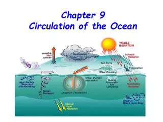
Why recover the 2-D structure of the ocean surface? • Characterize small scale wave dynamics • Air-sea interactions occur at short wavelengths • Non-linear interaction studies require phase-resolved surface topography • Enable through-the-wave imaging • Requirements • Spatial resolution (resolve capillary waves) ~ 1mm • Temporal resolution ~60Hz sampling rate • Shutter speed < 1 msec • Why use a passive optical technique • Probes disturb the air-sea interaction • Radar do not produce phase-resolved surfaces • Active techniques are complex and expensive
What is polarimetry? • Light has 3 basic qualities • Color, intensity and polarization • Humans do not see polarization
Linear Polarization http://www.enzim.hu/~szia/cddemo/edemo0.htm
Amount of circular polarization Orientation and degree of linear polarization Intensity What is polarimetry? • A bundle of light rays is characterized by intensity, a frequency distribution (color), and a polarization distribution • Polarization distribution is characterized by Stokes parameters S = (S0, S1, S2, S3) • The change in polarization on reflection or scattering is governed by Muller Calculus SOUT = M SIN • Where M contains information about the shape and material properties of the scattering media • The goal: Measure SOUT and SIN and infer the parameters of M Incident Light Muller Matrix Scattered Light
What is the Polarimetric Slope Sensing (PSS) technique? • Use the change in polarization of reflected skylight to infer the 2D surface slope, , for every pixel in the imaging polarimeter’s field-of-view
How well does the PSS technique work? • Conduct a feasibility study • Rented a linear imaging polarimeter • Laboratory experiment • setup a small 1m x 1m wavetank • Used unpolarized light • Used wire gauge to simultaneously measure wave profile • Field experiment • Collected data from a boat dock • Overcast sky (unpolarized) • Used a laser slope gauge
Looking at 90 to the waves Looking at 45 to the waves Looking at 0 to the waves
X-Component Y-Component Slope in Degrees
X-Component Y-Component Slope in Degrees
Build and Test an Imaging Polarimeter for Oceanographic Applications • Funded by an ONR DURIP • Frame rate 60 Hz • Shutter speed as short as 10 μsec • Measure all Stokes parameters • Rugged and light weight • Deploy in the Radiance in a Dynamic Ocean (RaDyO) research initiative http://www.opl.ucsb.edu/radyo/
Camera 3 Camera 4 Camera 1 (fixed) Polarizing beamsplitter assembly Objective Assembly Camera 2 Motorized Stage 12mm travel 5mm/sec max speed
FLIP INSTRUMENTATION SETUP Scanning Altimeters Visible Camera Air-Sea Flux Package Infrared Camera Polarimeter
Sample Results • A sample dataset from the Santa Barbara Channel experiment was analyzed • Video 1 shows the x- and y-slope arrays for 1100 frames • Video 2 shows the recovered surface (made by integrating the slopes) for the first 500 frames • A statistical comparison between our results and published results is given as well
Seeing Through Waves • Sub-surface to surface imaging • Surface to sub-surface imaging
Optical Flattening • Remove the optic distortion caused by surface waves to make it appear as if the ocean surface was flat • Use the 2D surface slope field to find the refracted direction for each image pixel • Refraction provides sufficient information to compensate for surface wave distortion • Real-time processing
Image FormationSubsurface-to-surface Observation Rays Air Water Imaging Array Exposure Center
Image Formationsurface-to-subsurface Exposure Center Imaging Array Air Imaging Array Water Exposure Center
Optical Flattening Algorithm • Collect polarimetric images • Compute the Stokes parameters for each pixel • Recover the 2D surface slope field • Compute the refraction for each rays as it passes through the air-sea interface • Create an undistorted image
Un-distortionA lens maps incidence angle θ to image position X θ Lens Imaging Array X
Un-distortionA lens maps incidence angle θ to image position X θ Lens Imaging Array X
Un-distortionA lens maps incidence angle θ to image position X Lens Imaging Array X
Un-distortionA lens maps incidence angle θ to image position X θ Lens Imaging Array X
Un-distortionA lens maps incidence angle θ to image position X θ Lens Imaging Array X
Un-distortionUse the refraction angle to “straighten out” light rays Distorted Image Point Image array Air Water
Un-distortionUse the refraction angle to “straighten out” light rays Un-distorted Image Point Distorted Image Point Image array Air Water
Real-time Un-Distortion • The following steps are taken Real-time Capable • Collect Polarimetric Images ✔ • Convert to Stokes Parameters ✔ • Compute Slopes (Muller Calculus) ✔ • Refract Rays (Lookup Table) ✔ • Remap Rays to Correct Pixel ✔
Detecting Submerged Objects“Lucky Imaging” • Use refraction information to keep track of where each pixel (in each video frame) was looking in the water column • Build up a unified view of the underwater environment over several video frames • Save rays that refract toward the target area • Reject rays that refract away from the target area
For more information contact Howard Schultz University of Massachusetts Department of Computer Science 140 Governors Drive Amherst, MA 01003 Phone: 413-545-3482 Email: hschultz@cs.umass.edu