Download
1 / 1
10 likes | 87 Views
Power. Lid. A time-lapse imaging system for documenting root response to environmental conditions Richard W. Zobel USDA-ARS Appalachian Farming Systems Research Center Rhizoecology - 1932-12000-004-00D 1224 Airport Rd Beaver, WV 25813. Scanner. Computer. Scanner ASM. Inlet Tube.

E N D
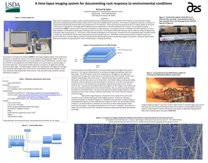
Power Lid A time-lapse imaging system for documenting root response to environmental conditions Richard W. Zobel USDA-ARS Appalachian Farming Systems Research Center Rhizoecology - 1932-12000-004-00D 1224 Airport Rd Beaver, WV 25813 Scanner Computer Scanner ASM Inlet Tube Nutrient Reservoir Outlet Tube Fog Generator Figure 4. Six perennial ryegrass clonal tillers in an ASM unit after one week. Lower portion is after 41 days of growth (This is the full image for the 12/07/07 segment of figure 6). Figure 1. A basic single unit ABSTRACT Plant roots normally grow in opaque media, necessitating destructive sampling techniques to determine their response to environmental changes. Destructive sampling frequently introduces artifacts and increases the variability within treatments. This results in a significant reduction in precision of measurement that becomes extreme with roots smaller than 0.2 mm diameter. If the requirement for physical structure is relaxed, plants can be grown in aeroponics or hydroponics, and images taken frequently and non-destructively. We have developed such a system. Our aeroponic scanning mesorhizotrons (ASM) consist of a bank of scanners controlled by a single computer. An individual scanner is modified to be water tight then a 10 mm deep chamber is constructed using the glass-scanning surface as one side. The chamber is fitted with entrance and exit tubes for aeroponic fog and slits in the foam sides to place plants in. The scanner is then oriented at 60 degrees from horizontal. Aeroponics can be manipulated under computer control to modify any environmental characteristic except physical structure based scenarios. With ASMs, we have demonstrated a cessation of grass root growth within hours of shoot clipping, and have characterized the developmental patterns of perennial ryegrass root systems. Aeroponic systems have been demonstrated to be appropriate for root x microbe studies, including mycorrhizae. Figure 3. An expanded view of an ASM Chamber An aeroponic scanning meso-rhizotron (ASM) for time-lapse imaging of plant roots need not be expensive: an inexpensive scanner, a PC, and an inexpensive fog generator (Table 1, Figure 1, 2, 3). Laboratory made fog generators can be assembled for about $100.00 each, a scanner is less than $75.00. In the preparation of the ASM chamber, care must be taken to seal the edges of the scanner glass face. If the scanner will be placed in an enclosure, all edges and openings need to be water-tight. The ASM chamber needs to be maintained at a 60 degree or less angle from horizontal with the glass face of the scanner on the bottom side of the chamber so that roots will grow along the glass face of the scanner. Inlet and outlet tubes should be opening downwards see figure 1. 1.25 cm thick foam spacer In the preparation of the ASM chamber, care must be taken to seal the edges of the scanner glass face. If the scanner will be placed in an enclosure, all edges and openings need to be water-tight. The ASM chamber needs to be maintained at a 60 degree or less angle from horizontal with the glass face of the scanner on the bottom side of the chamber so that roots will grow along the glass face of the scanner. Inlet and outlet tubes should be opening downwards, and the foam spacer can be sliced with a razor blade to allow inserting and holding the plants. Nutrient solutions can be any hydroponic nutrient mix. Since the roots have direct access to the ions in the droplets, the concentration needs to be less than normal. We use 12.5% or less. Fog hoses and manifolds need to be roughly 2 cm ID or larger, to not restrict flow and cause excessive condensation of the nutrient laden fog. We use continuous fog circulation, but others use intermittent flow. The later can be used to stimulate drought responses. Direct connection of the scanner with the computer by USB cable is the easiest method to produce and store images. Appropriate image frequency is dependent on the speed of the scanner, the resolution chosen and the specific goal of the imaging sequence. Frequency is the key to smooth presentation of sequential images, but calculation of growth rates and demonstration of developmental patterns can be made with one image every 24 hr. The second-order laterals of figure 6, are about 0.08 mm in diameter, but the meniscus of the adhering water makes them look much larger. The images presented here are 31.5 p mm-1 resolution. Root hairs are visible, but a resolution of 94 p mm-1 would be necessary to adequately determine their density and length. Figure 5. An operational 16 unit ASM System suitable for screening and replicated multifactor experiments. • Table 1. Minimum requirements, quick setup • Scanner • Epson V350 PHOTO* • Computer • PC with Vista OS* • Use "schedule a task" to periodically run Epson scan. • Fog generator • Equivalent to NutriMist 3*. http://www.nutramist.com/nutramistfogger.html • or, from scratch: http://www.oceanmistmaker.com/humidifierwholesales.html or • http://www.mainlandmart.com/foggers.html • for multiple ASM chambers, use: http://www.humidifirst.com/ • Supplies • Foam 1.25 cm thick • 1.25 cm O.D. CPVC pipe • 20 liter opaque polyethylene bottle with spigot. • Chemicals for Hoagland solution • Water • Small tripod for supporting scanner at 60° • Tubing • USB and power cables. • *USDA-ARS does not recommend these, but provides the information for the reader. A high through-put (figure 5.) precision system might include an A/D data logger with sensors and valves to control environmental parameters and nutrients, a custom digital switching board to switch between scanners (16 scanners per system), a high volume fog generator, LAN access to backup tapes. See patent #5,937,575 Figure 6. A sequence of images showing the initiation and growth of a dominant lateral root of Lolium perenne L. Small yellow horizontal lines are 1 cm long. Each image is of the same roots of clone LpAc 72. The indeterminate laterals are growing at the rate of 0.5 cm d-1, and the dominant lateral is growing at the rate of 1.5 cm d-1. Figure 2. A basic ASM system