Download
1 / 23
230 likes | 333 Views
Fabrication and testing of KGMT FSM prototype. Ho-Soon Yang, Hak-Yong Kihm, Il-Kwon Moon, Jae-Bong Song, Yun-Woo Lee Korea Research Institute of Standards and Science, Korea Young-Soo Kim Korea Astronomy & Space Science Institute, Korea. Oct. 4. 2010. Contents. Objective of project

E N D
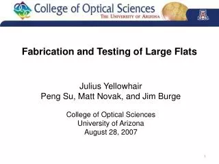
Fabrication and testing of KGMT FSM prototype Ho-Soon Yang, Hak-Yong Kihm, Il-Kwon Moon, Jae-Bong Song, Yun-Woo Lee Korea Research Institute of Standards and Science, Korea Young-Soo Kim Korea Astronomy & Space Science Institute, Korea Oct. 4. 2010
Contents Objective of project Recent experiences in KRISS Manufacturing flow diagram Optical testing Working cell design Future works
Objective • Technology development related to manufacturing of FSM for GMT project in advance • For FSMP • Use a model very close to FSM FSM prototype in KGMT project • Fabrication of FSMP with its own working cell designed by KRISS • Optical testing of FSMP after assembly with a cell (very close to real FSM cell)
Recent experiences @ KRISS • 800 mm lightweighted mirror for space application (1/2) Gravity Quilting (30 g/cm2) And other environmental effects …
Recent experiences @ KRISS • 800 mm lightweighted mirror for space application (2/2) • - Measurement of wavefront error with two different methods : • CGH (computer generated hologram) and conventional null lenses /30 rms CGH Conventional null lens
Recent experiences @ KRISS • 1 m off-axis paraboloid for collimator (1/2) • - Focal length = 6 m • - Distance between the center of OAP and optical axis = 700 mm Flat mirror OAP Interferometer
Recent experiences @ KRISS • 1 m off-axis paraboloid for collimator (2/2) OAP mirror Alignment telescope Interferometer Reference flat
Fabrication facilities in KRISS Measuring tower with null interferometer Rotating table with aspheric surface under test 1 m polishing machine 2 m polishing machine 2 m coating chamber Assembly room 2 m CNC machine 0.6 m polishing machine & testing tower
Manufacturing flow diagram 10% larger size Mirror blank procurement Curve generation Lightweighting Chemical Etching Rounding to target dimension Inspection Polishing Grinding Figuring (98%) Final figuring Inspection Assembly with cell Inspection FAT
Scheme of Optical testing • Efficient testing process is a key for successful fabrication of mirror Grinding Polishing Figuring Spherometer Profilometer ~ mm Profilometer Interferometer ~ μm Interferometer with CGH ~ nm
KRISS profilometer • Measurement accuracy ~ 1 um • Compensation of measurement errors of probe system using a high quality reference mirror Reference mirror
Interferometric testing using CGH 3 2 1 150 mm 4 CGH layout : (Line spacing : ~ 20 um) Adjustment between interferometer and CGH Test configuration of FSMP off-axis segment (off-axis type CGH )
CGH alignment 3 Adjustment I between CGH and FSMP segment 2 1 4 Adjustment II between CGH and FSMP segment
Testing tower setup KRISS Profilometer Turn-over tool
Testing configuration Optical testing after assembly with FSMP cell Optical testing during fabrication
Concept for working cell design Minimization of print through Load cell on the back plate of the mirror 24 axial support location Polishing pressure at the pocket of mirror with 0.1 psi
FE Model of M2 Top view bottom view Thin shell elements Material : Zerodur Diameter : 1064 mm Thickness : 140 mm Hole size : 100 mm Mass : 94 kg Face sheet : 20 mm Back plate : 14 mm Rib : 5 mm Web : 10 mm
Axial support y x Support locations
Print through Surface error Without correction PV 166 nm RMS 48 nm Surface error With correction PV 50 nm RMS 9 nm Displacement PV 165 nm Gravity z
Print through M2 structure function Gravity z
Surface error Surface error Without correction PV 110 nm RMS 31 nm Surface error With correction PV 35 nm RMS 6 nm Displacement PV 110 nm Quilting effect from polishing pressure of 0.1 psi
Surface error M2 structure function Polishing pressure 0.1 psi
Future works • Manufacturing of two types of CGH • Manufacturing of testing tower • Optimization of mirror working cell • Fabrication of FSMP by the end of next year • We hope to take parts in the fabrication of FSM in future