Download
1 / 24
240 likes | 347 Views
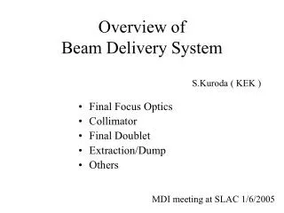
Overview of the Beam Interlock System. Beam Interlock System. “Target” system. BIS. Principle. User System #n. User #n-1. Beam_Permit. User. User System #3. “Target” system. AND. User_Permit#3. User System #2. User_Permit#2.

E N D
Overviewof the Beam Interlock System BIS Overview Linac4 BCC meeting / 21 Oct.2010 / B.Puccio (TE/MPE)
Beam Interlock System “Target” system BIS BIS Overview Linac4 BCC meeting / 21 Oct.2010 / B.Puccio (TE/MPE)
Principle User System #n User #n-1 Beam_Permit User User System #3 “Target” system AND User_Permit#3 User System #2 User_Permit#2 User System #1 Beam Source or Extraction kicker or Dump Kicker,… etc… User_Permit#1 BIS Overview Linac4 BCC meeting / 21 Oct.2010 / B.Puccio (TE/MPE) Σ (User_Permit = « TRUE » ) Beam_Permit = « TRUE »
Central part of LHC protection BIS Overview Linac4 BCC meeting / 21 Oct.2010 / B.Puccio (TE/MPE)
BIS Layout • BIS = set of Beam Interlock Controllers with 14+1 inputs each • BICs can be daisy chained • Two types of layout: ring or tree architecture (see next slide) • BIC boards embedded in VME chassis • Dedicated FESA class for monitoring and for remote testing • Supervision (JAVA application) for Operators JAVA Application • Dedicated User Interfaces (named CIBU) for connecting User System Permit signals via copper cable • Always installed in the User System rack • Input signal = current loop Technical Network #1 User System #1 Beam Permit Loops (F.O.) #2 User System #2 coppercables rear front view User Permit Beam Interlock Controller #14 User System #14 User Interfaces
Two types of layout ring architecture or tree architecture All BIC are identical.... except the “Master” BIC
Example of Master BIC: SPS Extraction (1/2) • Extraction_Permit for the Extraction kickers is generated by a “Master” BIC: • Simple ‘AND’ function replaced by combination of ‘OR of AND’ function • All inputs are NOT maskable • TED position is taken into account to ignore downstream inputs for necessary operational flexibility • Basic Principle: • Extraction_Permit = (TT60 BIC = OK) AND (TED = “IN position” ) • OR • (TT60 BIC = OK) AND (Ti2 BICs = OK ) • In taking into account the LHC injection region and the different conditions to inject a high intensity beam, we introduce another complication... Courtesy Verena Kain (BE/OP)
Example of Master BIC: SPS Extraction (2/2) Various operating modes: M1: Beam to upstream TED (setting up of the SPS extractions) M2: Beam onto downstream TED (setting up of the transfer line) M3: Probe beam into LHC (setting up of the LHC injections…) M4: Low intensity beam into LHC (filling the LHC) M5: High intensity beam into LHC (filling the LHC) Corresponding Truth Table for Master BIC:
System Performance Safe & Reliable:Safety Integrity Level 3 was used as a guideline Whole design studied using Military and Failure Modes Handbooks Results from the LHC analysis are: P (false beam dump) per hour = 9.1 x 10⁻⁴ P (missed beam dump) per hour = 3.3 x 10⁻⁹ Critical process in Hardware: ♦functionality into 2 redundant matrices ♦ VHDL code written by different engineers following same specification. Critical versus Non-Critical: ♦ Critical functionality always separated from non-critical. ♦ Monitoring elements fully independent of the two redundant safety channels. 100% Online Test Coverage: Can be easily tested from end-to end in a safe manner => recovered “good as new” Critical process in Hardware:functionality into 2 redundant matrices VHDL code written by different engineers following same specification. Critical versus Non-Critical: Critical functionality always separated from non-critical. Monitoring elements fully independent of the two redundant safety channels.
Masking “Flexible” system: thanks to Input Masking Within a fixed partition, half of User Permit signals could be remotely masked Setup Beam Flag FALSE Masking depends on an external condition: the Setup Beam Flag this SBF is generated by an independent system (like LHC Safe Machine Parameters system) and is distributed by the Timing system FALSE Masking automatically removed when this flag changes to FALSE FALSE YES
BIS monitoring: History Buffer time 11
BIS & Timing... • BIS process is independent of Timing • Beam_Permit changes when one of User_Permits changes • Nevertheless (thanks to Timing system) the BIS is synchronized to UTC time Timing Receiver board 1PPS tick Machine Timing Event pulse Beam Interlock Controller • In addition, an External hardware signal can create a record in the History Buffer • - like for the SPS Extraction lines with the Extraction Event occurrence Record created at the external pulse occurrence Useful for checking time relationship Interlock’s change Vs. Machine event 12
BIS Output: Beam Permit signals ♦ For Beam_Permit _A: Nominal Frequency 9.375MHz => Period = 107ns Duty cycle 50% ♦ For Beam_Permit _B: Nominal Frequency 8.375MHz => Period = 119ns ♦ Beam_Permit is TRUE is corresponding frequency is detected ♦ absence or erroneous frequency means that Beam_Permit is FALSE. BIS Overview Linac4 BCC meeting / 21 Oct.2010 / B.Puccio (TE/MPE) Both Beam_Permits transmitted via Fibres Conversion Electrical/light and Light/electrical performed by a dedicated board
BIS User Interface (named CIBU) User _ Permit _ A+ User _ Permit _ A- Unique HW solution for connecting any User System to the BIS Front view rear view to Beam Interlock Controller User System CIBU ( could be PLC based, or VME based, or any type of electronics…) BIS Overview Linac4 BCC meeting / 21 Oct.2010 / B.Puccio (TE/MPE) User_Permit state transmitted in RS485 format Current loop signal User_Permit = “TRUE” if input current > ~10mA
BIS User Interface details BIS Overview Linac4 BCC meeting / 21 Oct.2010 / B.Puccio (TE/MPE) • Fast response time (2.6 µS max) • Large Input Voltage Range ( 4V up to 25V) • Input TVS Diodes (33Volts) to protect overvoltage • Input current limitation stage • Hysteresis, clean signal edges • RS485 output, good EMC, long distance (up to 1200m) More details in EDMS #636589
BIS User Interface input User Interface (CIBU ) Shielded & Twisted Pair cable User Side + 25Vmax <5 meters User_Permit_B User_Permit_A BIS Overview Linac4 BCC meeting / 21 Oct.2010 / B.Puccio (TE/MPE) 0V Mandatory circuit: All ground / earth / 0V connected Spare wires grounded Shield 360o at both ends & NO pig-tails Cable should be Twisted pair (like NE8 type) or LEMO 00 from VME front-panel More than 5 meters = FORBIDEN Same circuit for “B” channel
Summing up • Initially designed for LHC => Highly reliable, Fast and Maintainable • Modular and expandable • Deployed in SPS ring and Transfer lines SPS-CNGS-LHC • Tree architecture suitable for Linac4 requirements • Slave BICs : “AND” function of 14+1 inputs • with fixed Unmaskable/ Maskable partition • Master BIC : “AND” & “OR” functions of 14+1 inputs • (like local Beam_Permits, User_Permits, Beam Conditions Flags…) • In both cases, an input for Software Interlock allows more flexibility. BIS Overview Linac4 BCC meeting / 21 Oct.2010 / B.Puccio (TE/MPE) • Redundant Beam_Permits = Fixed Freq. signals available of optical cables • Unique Hw solution to interface any type of electronics • User_Permits = simple current loops ( with I >10mA ) • Redundant signals are required • Interconnecting recommendations have to be followed
Thank you ! BIS Overview LINAC4 WP presentation meeting 17 Feb.09 / B.Puccio (TE/MPE)
Backup slides BIS Overview LINAC4 WP presentation meeting 17 Feb.09 / B.Puccio (TE/MPE)
Electrical Architecture (LHC case) Electrical Architecture in USER rack in INTERLOCK rack Cable User System 2U Chassis VME Chassis Courtesy BenjaminTodd
Kickers only pulse if they have the PERMIT • ...and if energy is correct (BETS = beam energy tracking system) and for the injection kicker: if the abort gap keeper (AGK) gives green light → see Jan’s talk • LHC injection kicker needs: injection permit (produced by the Injection BICs) • SPS extraction kicker needs: extraction permit (produced by the Extraction master BIC) • Injection permit = LHC beam permit + injection BICs OK • Extraction permit = injection permit + transfer line BICs OK + extraction BICs OK + • + combination of flags Courtesy Verena Kain (BE/OP)
User Interface: remote test & monitoring Test and Monitoring of USER_PERMIT Channel (signals in green)
BIS Hardware User Interface Optical daughter cards Redundant P.S. Manager Test & Monitoring ~2200 boards produced (~85% in operation) F.O. variant of the User Interface Back Panel User system’s side Controller’s side