Download
1 / 38
390 likes | 512 Views
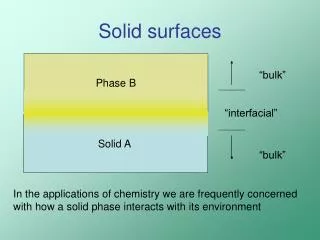
When Sound Waves meet Solid Surfaces. Applications of wave phenomena in room acoustics By Yum Ji CHAN MSc (COME) candidate TU Munich. 0 Introduction. Phemonena of sound waves Equipments on surfaces to control sound intensity Applications in room acoustics

E N D
When Sound WavesmeetSolid Surfaces Applications of wave phenomena in room acoustics By Yum Ji CHAN MSc (COME) candidate TU Munich
0 Introduction • Phemonena of sound waves • Equipments on surfaces to control sound intensity • Applications in room acoustics • Numerical aspects of finite element method in acoustics • Conclusion
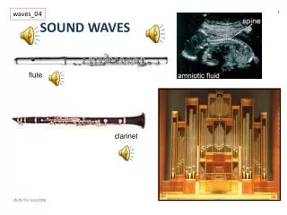
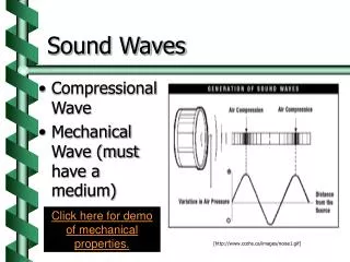
1.0 Nature of sound • Sounds are mechanical waves • Sound waves have much longer wavelength than light • Speed of sound in air c ≈ 340m/s • Wavelength for sound λ • c = f · λ • When f = 500 Hz, λ = 68 cm • Typical wavelength of visible light= 4-7 × 10⁻⁷ m • Conclusion • Rules for waves more important than rules for rays
1.1 Measurement of Sound intensity • Acoustic pressure in terms of sound pressure level (SPL) • Unit: decibel (dB), pref = 2 × 10⁻⁵ Pa • Acoustic power • More parameters are necessary in noise measurements (out of the scope)
1.2 Huygen’s principle • From wikipedia: • It recognizes that each point of an advancing wave front is in fact the center of a fresh disturbance and the source of a new train of waves; and that the advancing wave as a whole may be regarded as the sum of all the secondary waves arising from points in the medium already traversed. • Diffraction & Interference apply
1.3 Diffraction & Interference • Edge interference due to finite plates • Reflection on flat surface: Deviation from ray-like behaviour
1.4 Fresnel zone • Imagine each beam shown below have pathlengths differered by λ/2 • What happens if… • Black + Green? • Black + Green + Red?
1.5 Conclusion drawn from experiment • Theory for reflectors in sound is more complicated than those for light • Sizing is important for reflectors
2.0 Elements controlling sound in a room • Reflectors • Diffusers • Absorbers
2.1 Weight of Reflectors • Newton’s second law of motion: • Difference in acoustic pressure = acceleration • Mass is the determining factor at a wide frequency range • Transmitted energy (i.e. Absorption in rooms) is higher • At low frequencies • When the plate is not heavy enough
2.2 Size of Reflectors • Never too small • Diffraction • Absorption • No need to be too big • Imagine a mirror for light! • Example worksheet
Type 2 2.3 Diffusers • Scattering waves • With varied geometries Type 1
2.4 Absorbers • Apparent solution: Fabrics and porous materials • Reality: it is effective only at HF range • Needed in rooms where sound should be damped heavily (e.g. lecture rooms) • Because clothes are present • Other absorbers make use of principles in STRUCTURAL DYNAMICS
2.5 Absorption at other frequency ranges (A) • Hemholtz resonator-based structures • Analogus to spring-mass system • Example worksheet • The response around resonant frequency depends on damping • Draw energy out of the room (Source: http://physics.kenyon.edu/EarlyApparatus/index.html)
2.6 Absorption at other frequency ranges (B) • Low frequency absorbers • Plate absorbers, make use of bending waves • Composite board resonators (VPR in German)
2.7 Comparison between a composite board resonator and a plate • VPR Resonator assembly • Modelled as a fluid-solid coupled assembly with FE • Asymmetric FE matrices (Owner of the resonator: Müller-BBM GmbH) (Source: My Master’s thesis)
2.7 Asymmetric FE matrices • FE matrices are usually symmetric • Maxwell-Betti theorem • Coupling conditions make matrices asymmetric
Characteristiceigenfrequencyof the resonator 2.7 Comparison between a composite board resonator and a plate • Bending waves without air backing (Uncoupled, U) • Compressing air volume with air backing (Coupled, C) (Source: My Master’s thesis)
2.8 Why is it like that? • Consider Rayleigh coefficient • Compare increase of PE to increase of KE Compression Vibration
3 Parameters in room acoustics • Reverberation time • Clarity / ITDG (Initial time delay gap) • Binaural parameter
Direct sound First reflections (early sound) Energy 1 2 3 4 Reverberation Time Time 3.1 Impulse response function of a room • The sound profile after an impulse (e.g. shooting a gun or electric spark in tests) (Courtesy of Prof. G. Müller)
3.2 Reverberation time • The most important parameter in general applications • Definition: SPL drop of 60 dB • Formula drawn by Sabine • Depends on volume of the room and “the equivalent absorptive area” of the room • Samples to listen: • Rooms with extremely long RT: Reverberant room (Courtesy of Müller-BBM)
Direct sound First reflections (early sound) Energy 1 2 3 4 Reverberation Time Time 3.3 Clarity / ITDG • Clarity: Portion of early sound (within 80 ms after direct sound) to reverberant sound • ITDG: Gap between direct sound and first reflection, should be as small as possible
3.4 Binaural parameter • Feel of spaciousness • The difference of sound heard by left and right ears
3.5 Applications: Reverberant room • Finding the optimum positions of resonators in the test room (Source: My Master’s thesis)
3.5.1 Application: Reverberant room • Mesh size 0.2 m • ~ 30000 degrees of freedom • Largest error of eigenvalue ~ 2%
3.5.2 Impulse response function • Reverberation time • The effect of amount of resonators • The effect of internal damping inside resonators (Source: My Master’s thesis)
3.5.3 Getting impulse response functions • Convolution • “Effect comes after excitation” • Mathematical expression • Expression in Fourier (frequency) domain Y(f) = X(f) H(f) • X(f) = 1 for impulse • H(f) = Impulse response functionin time domain
3.5.3 Getting impulse response functions • Frequency domain • Time domain
3.6 Are these all? • Amount of parameters are increasing • Models are still necessary to be built for “acoustic delicate” rooms • Concert halls
3.7 A failed example • New York Philharmonic hall • Models were not built • Size of reflectors (Source: Spektrum der Wissenschaft)
4.1 Acoustic problems with the finite element (FE) method • Wave equation • Discretization using linear shape functions • Variable describing acoustic strength • Corresponding force variables
4.2 1D Example • 100 m long tube, unity cross section • Mesh size 1 m, 2 m and 4 m
4.2 1D Example • Discretization error in diagram
4.3 Numerical error • Possible, but not significant if precision of storage type is enough
5 Conclusion • Is acoustics a science or an art?`