Download
1 / 2
20 likes | 144 Views
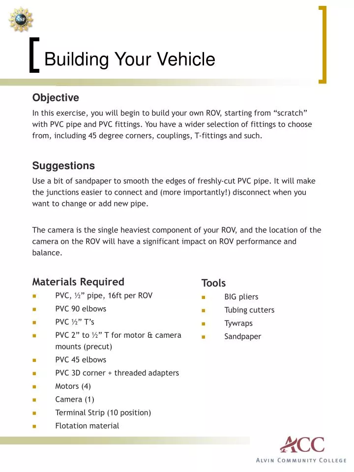
Building Your Vehicle. Objective In this exercise, you will begin to build your own ROV, starting from “scratch” with PVC pipe and PVC fittings. You have a wider selection of fittings to choose from, including 45 degree corners, couplings, T-fittings and such. Suggestions

E N D
Building Your Vehicle Objective In this exercise, you will begin to build your own ROV, starting from “scratch” with PVC pipe and PVC fittings. You have a wider selection of fittings to choose from, including 45 degree corners, couplings, T-fittings and such. Suggestions Use a bit of sandpaper to smooth the edges of freshly-cut PVC pipe. It will make the junctions easier to connect and (more importantly!) disconnect when you want to change or add new pipe. The camera is the single heaviest component of your ROV, and the location of the camera on the ROV will have a significant impact on ROV performance and balance. Materials Required • PVC, ½” pipe, 16ft per ROV • PVC 90elbows • PVC ½” T’s • PVC 2” to ½” T for motor & camera mounts (precut) • PVC 45 elbows • PVC 3D corner + threaded adapters • Motors (4) • Camera (1) • Terminal Strip (10 position) • Flotation material Tools • BIG pliers • Tubing cutters • Tywraps • Sandpaper
Building Your Vehicle Wiring Your ROV As you design your ROV, determine where the tether will attach to the frame. Near that point, attach the 10 position terminal strip using tywraps. This terminal strip will serve as a connection point between the tether and the motors on the ROV. As you install the motors, attach the motor wires to the terminal strip as shown below. Be careful to keep the motor wiring ‘pairs’ together; motor #1 is the PORT HORIZONTAL THRUSTER and is connected to locations 1 and 2; motor #2 is the STARBOARD HORIZONTAL THRUSTER and is connected to locations 3 and 4. VERTICAL THRUST Motors #3 and #4 are connected to locations 5-6 and 7-8. Locations 9-10 are not used in this design. Vertical Thruster #2 MOTOR #4 Vertical Thruster #1 MOTOR #3 ROV Terminal Strip Starboard Horizontal Thruster MOTOR #2 Port Horizontal Thruster MOTOR #1