Download
1 / 70
710 likes | 859 Views
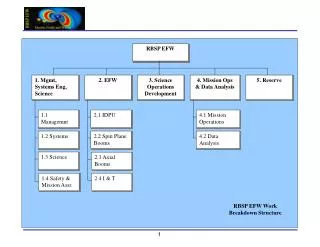
EFW AXB. Spacecraft +Z. Jeremy McCauley Aerospace Engineer Space Sciences Laboratory, UCB jeremymc@ssl.berkeley.edu. AXB. AXB. EFW AXB Overall Flow. Design. PDR. ETU Build. ETU Test. Peer Review July 28. Flight DWG Release. PDR RFAs: 6 AXB related, 6 Closed Peer Review

E N D
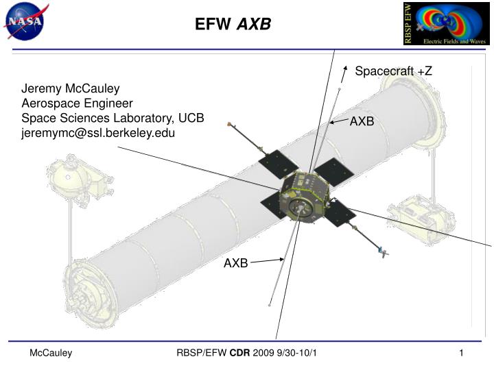
EFW AXB Spacecraft +Z Jeremy McCauley Aerospace Engineer Space Sciences Laboratory, UCB jeremymc@ssl.berkeley.edu AXB AXB RBSP/EFW CDR 2009 9/30-10/1
EFW AXBOverall Flow Design PDR ETU Build ETU Test Peer Review July 28 Flight DWG Release • PDR • RFAs: 6 AXB related, 6 Closed • Peer Review • AIs: 4 AXB related, 4 implemented • Suggestions: 11 AXB related, 11 implemented • CDR • RFAs: 0 (?) CDR Flight Build EFW INST+SOC PEER REVIEW
EFW AXBOverview • Design Drivers • Design Description • Concept • Heritage • Assembly Breakout • Thermal • ETU Integration and Testing (I&T) • Changes Since ETU RBSP/EFW CDR 2009 9/30-10/1
EFW AXBDesign Drivers • Deploy spherical electric fields probes up to 7 meters from center of spacecraft with an E-Field sensor and preamp at the end. • Length adjustable (longer only) on orbit with a resolution of +/- 0.5 cm • Interface to spacecraft to support deployable booms. • Meet straightness requirement (< 1° from spin axis). • Provide relief for CTE mismatch between Gr/E Tube and SC body. • Provide a connector for test input to the sensor accessible during all integration phases. • Total Mass not to exceed 8.57 kg (Each AXB Unit to not exceed 3.64 kg; AXB Tube to not exceed 1.29 kg) • Interface Operational Temperature Range: -25 to +55C (TBR) • Interface Survival Temperature Range: -30 to +60C (TBR) RBSP/EFW CDR 2009 9/30-10/1
EFW AXBConcept Upper Boom Unit (+Z) Lower Boom Unit (-Z) • Axial Boom Unit (AXB) • Sensors Extended from SC on Stacers • Compact for Launch • Rigid after Deploy • Adjustable Length RBSP/EFW CDR 2009 9/30-10/1
EFW AXBHeritage • Heritage Unit • Primarily AXB from THEMIS, modified for length and to fit RBSP SC • Including Tube, Structure, Stacer, DAD design and springs • Similar to units on STEREO (6), THEMIS (10), POLAR and FAST • More than 60 years of on orbit operation • Whip from Rockets • replaces THEMIS Whip Stacer • Direct Drive Unit from THEMIS SPB • Added Refinements • Direct Drive Unit on a Stacer • DAD Lock Wheel Assemblies • Sphere Caging Mechanism RBSP/EFW CDR 2009 9/30-10/1
EFW AXBOrder of Deploy • Stowed Unit • Unpowered • Fully Restrained • Step 1: Whip Deploy • Frangibolt Actuated • Spring Powered +Z SC Axis • Step 2: Stacer Deploy • Frangibolt Release • Motor Driven (3 cm/s) • Length Adjustable • Fault Analysis in Backup Slides RBSP/EFW CDR 2009 9/30-10/1
EFW AXBDesign Description: AXB Upper Boom Unit (+Z) Lower Boom Unit (-Z) • Structural Design • End Supported Tube with Aluminum End Fittings • Two (2) Identical Boom Units • Stationary Deploy Assembly • Moving DAD • Stacer • Whip and Spherical Electric Fields Probe RBSP/EFW CDR 2009 9/30-10/1
EFW AXBTube Assembly • Structural Design • End Supported Tube: Graphite Epoxy, M55 (Layup: -60/60/0/0/60/-60 [quasi-isotropic]) • Fixed-Fixed First Frequency: 257 Hz • Tube Static Stress Margin: 10 • End Fittings: Al 6061-T6 • Lower Support includes a drumhead flexure design • Currently 89.1 lbf @ 52ºC dT • Joint Epoxy: Hysol 9309NA • Bond Shear Stress Margin: 30.3 Flexure Tube End Fitting Flexure at dT=52ºC RBSP/EFW CDR 2009 9/30-10/1
EFW AXBTube Testing • Structural Testing • Thermal cycling • Static loads • Structural loads testing • Integrated to SC RBSP/EFW CDR 2009 9/30-10/1
EFW AXBDesign Description: Booms Stowed Configuration • Boom Design • Stationary Deploy Assy • Moving DAD • Stacer • Whip and Spherical Electric Fields Probe Whip Deploy Assy DAD Stacer Deployed Configuration RBSP/EFW CDR 2009 9/30-10/1
EFW AXBDesign Description: Booms Stowed Configuration • Stationary Deploy Assy • Sphere Caging Mechanism • Direct Drive Assembly • Roller Nozzle #1 Sphere Caging Mechanism Direct Drive Assy Roller Nozzle #1 Deployed Configuration RBSP/EFW CDR 2009 9/30-10/1
EFW AXBDesign Description: Cage Stowed Configuration • Sphere Caging Mechanism • Protect Spherical Electric Field Probe • Release Whip on Orbit • Frangibolt Actuator (Next Slide) • Top Opens • Cam Releases Arm • DAD Plunger with Kickoff Spring Starts Whip • AC Test Contact for Ground Operations • Torque Margin: 40.9 • Spring to Friction Drag • Green Tag Enable Plug/ Ground Test Plug DAD Plungers Frangibolt AC Test Contact Enable Plug Deployed Configuration RBSP/EFW CDR 2009 9/30-10/1
EFW AXBDesign Description: Frangibolt • TiNi Frangibolt • 500 lb Retention Force • For Launch Loads Only • Static Margin: 14 • Resettable • 25 W @ 28 Vdc • 95°C Actuation Temperature • Trending Data RBSP/EFW CDR 2009 9/30-10/1
EFW AXBDesign Description: Direct Drive Frangibolt Slip Ring Motor Sense Switches Spool • Direct Drive Assembly • Stacer Frangibolt Release • Harness Spool: Max Capacity 6.66 meters 0.068” diameter cable • Motor Drive Mechanism: Globe A1430 Motor (1000:1 gear ratio) • Sense Switches: Stacer Release, End of Wire and Turn Counter (Newark, 1HM19) • Slip Ring (Airflyte CAY-1398) • Length Resolution: 0.65 cm/click BOT, 0.52 cm/click EOT, 5.2 clicks/s • Torque Margin: 7.6 (Motor Torque to Torque to Retract Stacer) Harness RBSP/EFW CDR 2009 9/30-10/1
EFW AXBCable Load Path Glue Joint • Cable Force Path • Force is carried completely in Kevlar overwrap • Static Margin: >100 Tie Off Point RBSP/EFW CDR 2009 9/30-10/1
EFW AXBDesign Description: Nozzle • Roller Nozzle #1 • Centering of the Stacer • Resist SC Forces • Springs designed to 1.6 lb minimum radial force Rollers Rocker Arms RBSP/EFW CDR 2009 9/30-10/1
EFW AXBDesign Description: DAD • Moving DAD • Deployment Assist Device (DAD) with Kickoff Springs • Lock Wheel Assemblies • Increase Unseat Force from 6 lbs to 15 lbs axial from 1.6 to 4.5 lbs radial • Roller Nozzle #2 • Springs designed to 1.6 lb minimum radial force • Force Margin: 2.1 • DAD Springs to Friction Roller Nozzle #2 DAD Springs Lock Wheel Assy Stowed Configuration Deployed Configuration RBSP/EFW CDR 2009 9/30-10/1
EFW AXBDesign Description: Stacer • Stacer • Helical Spring • Deployed Acts as a Rigid Tube • Spin Adjusted Resonance: 26.5 RPM • Force Margin: > 3 • Stacer Force to Friction Deployed Configuration Stacer RBSP/EFW CDR 2009 9/30-10/1
EFW AXBDesign Description: Whip Stowed Configuration • Whip and Spherical Electric Fields Probe • Hinge • Torque Margin: 3.6 • Hinge Spring to Friction • DAG 213 Coated • Whip Tube • FOS (Bending on Deploy): 2.0 • DAG 213 Coated • Sphere • Probe and Preamp Assy • DAG 213 Coated • Cannot Clean DAG 213 surfaces • All Three Isolated for Potential Control • Fundamental Frequency: 23.0 RPM • (> 4x SC Spin Rate Rigid) Sphere Internal View Preamp Hinge Whip Sphere Deployed Configuration RBSP/EFW CDR 2009 9/30-10/1
EFW AXBDesign Description: Stress Margins RBSP/EFW CDR 2009 9/30-10/1
EFW AXBGlue Bond Margins * Joint Strength is derated according to surface preparation requirements as discussed in HTN-102050-017, dated 06/15/2000, as received from Chris Smith, UCB/SSL. RBSP/EFW CDR 2009 9/30-10/1
EFW AXBGlue Bond Margins Whip to Hinge Whip to Sphere DAD Rod to DAD Tip Tip Tube to Tip End Tip to Tip Tube Tip to Safety Pin RBSP/EFW CDR 2009 9/30-10/1
EFW AXBDesign Spreadsheets • Caging Spring Torque • DAD Lock Spring • DAD Telescoping Spring • Deploy Motor • Frangibolt Firing Times • Hinge CTE • Hinge Spring Torques • Large Fine Pitch Bolt Torques • Mass Properties • Roller Nozzle Spring • Sense Line Resistances • Tube CTE • Whip Torsion Spring • Wire and Spool RBSP/EFW CDR 2009 9/30-10/1
EFW AXBThermal • Thermally Coupled to the SC • Spherical Electric Fields Probe, Whip and Hinge: • Coated with DAG 213 • Stacer: • Mill Finish Elgiloy • Moving DAD: • Alodine (1500, Clear, 300s immersion) • Electroless Nickel Plating with Teflon Impregnate • Stationary Deploy Assy: • Alodine (1500, Clear, 300s immersion) • Electroless Nickel Plating with Teflon Impregnate • End Supported Tube • M55 Graphite Epoxy • Aluminum End Fittings • Alodine (1500, Clear, 300s immersion) RBSP/EFW CDR 2009 9/30-10/1
EFW AXBLong Lead Items • Frangibolts • Ordered: August 2009 • ~10 week lead • Gore Cable • In House • Motor • In House • Stacer • In House EFW INST+SOC PEER REVIEW
EFW AXBOrder of Assembly Assemble Caging Mech Preamp Mech Assembly Test Preamp PWB Whip and Cage Mechanical Functional Integrate Whip and Cage Assemble Sphere, Whip and Preamp Assemble Whip Paint: Whip, Stacer and Sphere Whip and Cage Electrical Functional Assemble Stacer Assemble Stacer Assembly Assemble Doors Assemble DAD Assemble Stacer Mechanism Motor Burn In Harness Motor Harness Assembly Harness SW1 Assemble Direct Drive (-500) StacerMech Functional,Length & Runout Measurement, Continuity Check Harness Diode Block PER EFW INST+SOC PEER REVIEW
EFW AXBI&T: Environmental Test Matrix RBSP/EFW CDR 2009 9/30-10/1
EFW AXBEnvironmental Testing Integrate Stacer, Whip and Cage Integrated Vibration Test PER Electrical Functional Test Electrical Functional Test StacerMech Functional,Length & Runout Measurement, Continuity Check Whip and Cage Mechanical Functional Dis-Integrate Stacer, Whip and Cage Electrical Functional Test Whip and Cage TV Hot Deploy Whip and Cage TV Cold Deploy Integrate Stacer, Whip and Cage Mass Properties Science Calibration StacerMechTV Hot Deploy,Length & Runout Measurement, Continuity Check StacerMechTV Hot Deploy,Length & Runout Measurement, Continuity Check PSR EFW INST+SOC PEER REVIEW
EFW AXBI&T: Deployments • Functional Deployments • Expected number of deployments on the instrument at launch: 4 • Functional • Post Vibe Functional (“test as you fly” exception) • Thermal Vacuum Hot • Thermal Vacuum Cold • Deployments of Whip and Cage at SC Level after Vibe All stacer deployments include: Frangibolt and Motor trending, EOT Switch verification, Continuity verification, Runout and Stiffness testing. RBSP/EFW CDR 2009 9/30-10/1
EFW AXBI&T: Alignment • Alignment Testing • Requirement: <1° from spin axis • Testing Total: <2.2” Runout < 0.46° from spin axis • Stacer Runout is <1.2” (0.88”, 0.73”, 1.2”, 1.2”, 0.94”) • Unit deployed horizontally on a g-negating track, then lifted to floats. • RSS Analysis of Tolerance Stackup: 0.20 degree (0.8 inches at Sphere) • Hinge, Whip and Sphere Runout is <0.1” • Loose Stacer on Tip 0.1” • Stiffness: 0.003 lb/in • Fund. Frequency: 0.43 Hz RBSP/EFW CDR 2009 9/30-10/1
EFW AXBI&T: Vibration • Vibration Testing • ETU Vibration to Qualification levels per 7417-9019 Section 5.4.5 • Self-shock survival from boom deployment actuations • Force Limiting (C^2 = 5, f(0) = 1.1 X f(n), CG response = 4.25 X TLL) • First Frequency: X, Y = 180 Hz, Z = 275 Hz • Flight Units Random to GEVS Workmanship Levels as these are higher than the SC loads predicted by early SC acoustic testing. RBSP/EFW CDR 2009 9/30-10/1
EFW AXBI&T: TV • Thermal Vacuum Testing • 2 operational cycles plus 1 survival cycle, per the requirements and limits indicated in 7417-9019 section 5.3.2 • Deployment tests successful at hot and cold levels HOT DEPLOY COLD DEPLOY RBSP/EFW CDR 2009 9/30-10/1
EFW AXBRadiation Dose Testing • Three samples were analyzed: • a 2 square inch sample of Aluminum with Electroless Nickel Plating with Teflon Impregnate (Microlube, by Micro Plating, Inc.), • approximately 2 feet of AXB harness with Tefzel overwrap (Gore Cable, RCN8818, July 2008), and • a hemisphere coated with DAG-213. • Total dose of 10 Megarads at 18 rads/s, • Average gamma ray photon energy is 1.25 MeV. • APL Space Departments Cobalt 60 Irradiator • Maintained integrity, adhesion and surface properties. RBSP/EFW CDR 2009 9/30-10/1
EFW AXBMass Properties Testing • Mass Properties Testing: to be completed • Mass: 3.065 kg (2.97 predict, 3.40 NTE) • 11% Margin • Ixx = 0.160 kg-m2 (0.407 kg-m at Tube COM) • Iyy = • Izz = RBSP/EFW CDR 2009 9/30-10/1
EFW AXBHYPOT Testing • HYPOT Testing: to be completed • Connectors need testing for resistance to High Potential (HI POT) • Not reasonable on a part by part basis • Harness will be tested in unit, prior to Preamp installation Whip Hinge Whip Harness Sphere RBSP/EFW CDR 2009 9/30-10/1
EFW AXBAnomaly Reports • CLOSED • RBSP_EFW_AXB_018 Disposition of Deploy Catch 090417 • Improved Stacer Packing • Tip Grip Accommodated in Alignment • RBSP_EFW_AR_003 AXB Motor Gap • Washer on ETU to fill gap • No modification to Flight Motors • RBSP_EFW_AR_004 Frangibolt Overtemp in Hot TV • Switches with Timing Backup • OPEN • RBSP_EFW_AR_002 AXB Spool Wiring • Open conductor • Pending further testing RBSP/EFW CDR 2009 9/30-10/1
EFW AXBChanges Since PDR • Increase deploy length from 12m to 14m tip to tip. • Maintaining extra coils in Stacer Can. • Removed Deploy Heater and Thermostat. • Determined unnecessary in EFW/SOC PDR AI #29. • Change Roller Nozzle Springs. • Lowered contact force. RBSP/EFW CDR 2009 9/30-10/1
EFW AXBChanges Since ETU Testing • Add Frangibolt Switches RBSP/EFW CDR 2009 9/30-10/1
EFW AXBChanges Since ETU Testing • Add Science Cable support on Direct Drive Assembly • Spool Wheel Well • Finalize Spool Sizing RBSP/EFW CDR 2009 9/30-10/1
EFW AXBChanges Since ETU Testing • PreAmp Harness Support • Additional travel range added to Sphere Clamps • Improve bonding features around Omnetics connectors • Add clearance to parts near stacer • Add Sleeve for Sphere Cage Stop RBSP/EFW CDR 2009 9/30-10/1
EFW AXBShipping Containers • Designed and Assembled • Vibration Shipping Crate • Tube Shipping Crate • To Be Completed • Final Crate for Shipment to APL • 2 Whips • 2 Cages • 2 Deploy Assemblies • Not Assembled • Most likely an update to the Vibration Shipping Crate RBSP/EFW CDR 2009 9/30-10/1
EFW AXBBackup Slides • Back up slides • Redundancy is Key…. RBSP/EFW CDR 2009 9/30-10/1
SSL History / Heritage UCB/SSL HERITAGE(courtesy F. Mozer) Spacecraft SPB’s AXB’s Mag Booms S3-2 4 S3-3 4 2 ISEE 2 VIKING 4 FREJA 6 FIREWHEEL* 2 CRRES 2 POLAR 4 2 FAST 4 2 2 CLUSTER I* 16 CLUSTER II 16 THEMIS 20 10 10 SPARES 26 6 2 Lunar Prospector 1 Sounding Rockets ~50 ----- ----- ----- 110 26 (+ 50) 15 * LAUNCH FAILURE McCauley RBSP/EFW CDR 2009 9/30-10/1
EFW AXBDesign Description RBSP/EFW CDR 2009 9/30-10/1
EFW AXBDesign Description RBSP/EFW CDR 2009 9/30-10/1
EFW AXBDesign Description RBSP/EFW CDR 2009 9/30-10/1
EFW AXBDesign Description RBSP/EFW CDR 2009 9/30-10/1
EFW AXBDesign Description RBSP/EFW CDR 2009 9/30-10/1
EFW AXBDesign Description RBSP/EFW CDR 2009 9/30-10/1