Download
1 / 20
210 likes | 352 Views
Magnetic Shielding and Creation of homogeneous magnetic field for RF cavity. Research student: Gustavo A. Gandara Montano Supervisor: Bertalan Juhasz. ASACUSA Collaboration. Thursday August 12 th , 2010. Rm 160-1-009 at CERN. Geneva, Switzerland. The Big Picture (1).

E N D
Magnetic Shielding and Creation of homogeneous magnetic field for RF cavity Research student: Gustavo A. Gandara Montano Supervisor: Bertalan Juhasz ASACUSA Collaboration Thursday August 12th, 2010. Rm 160-1-009 at CERN. Geneva, Switzerland
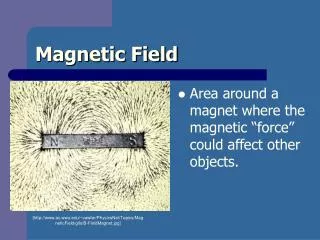
The Big Picture (1) • The ASACUSA Collaboration is trying to measure hyperfine splitting of Antihydrogen *HyperPhysics Inhomogeneity requirement of 2% What can you get from this experiment? CPT test and antiproton magnetic moment measurement * B. Juahasz, E. Widmann
What I am trying to do: RF cavity: Radius of 210 mm Length 100 cm Region of Homogeneity: Radius: 100 mm Length: 105 mm (HAW) Initial Situation Inhomogeneity of 44.28%
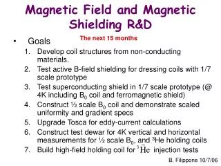
How to produce the homogeneous Field? Garrett Coils Smaller Garrett Coil: Laying along Z axis, it exists inside a sphere of 250 mm Larger Garrett Coil: Laying along Y axis, it exists inside a sphere of 300 mm Inhomogeneity well below 0.01% For both Garret Coils to produce the same magnetic field at the center. The external Coil must have a current larger by a factor of 1.2
An inherent problem with the shielding Graphs created by the Garret Coils and cylinders laying along Z-axis ONLY Mu metal Soft Iron The induced field introduces inhomogeneity that can go from 0.2 % to 0.6 % *The Garret Coils would create a field of 3.0 G in this set up
First geometry: • Cusp Trap Shielding and cylinder laying along z-axis surrounding the cavity • The parameters of the cusp trap shielding that gave the less external field in the region of homogeneity were: A length of 100 mm, a location of -550 mm and a Radius of 1000 mm. (This gave a |B| of 0.39697 G at {50,0,-53}) * You have to optimize the whole setup at the same time!!! • Terrible job. Inhomogeneity of 12%
Best Optimizations: Shielding along Z-axis Cusp Shielding: Radius=500 Length=270 Location=-800 RF shielding: Radius 650 mm Length=776 Shielding along X-axis Cusp Shielding: Radius=500 Length=220 Location=-850 RF shielding: Radius 550 mm Length=776 {x,0,z} plane {0,y,z} plane Inhomogeneity of 0.6 % in YZ plane Inhomogeneity of 0.91 % in YZ plane.
An inconsistency with the software XZ Plane YZ Plane 2,2,2 divisions. B field goes from 3.182 to 3.186 in YZ Plane. Inhomogeneity: 0.12% 3,3,3 divisions. B field goes from 3.310 to 3.295 in YZ Plane. Inhomogeneity: 0.45% 2,2,4 divisions. B field goes from 3.23 to 3.25 in YZ Plane. Inhomogeneity: 0.61%
First task: Build the sextupole in CST Cavity region Close to the sextupole
Some optimum configurations I tried with CST (I am showing some of many configurations) * Cusp shielding made of iron. Has radius=500 Length=270 Left side at=-800 • Initial results obtained in CST: • Box shielding is less efficient than cylindrical • A sextupole shielding (with a side) improves considerably the situation • Adding a second layer of shielding makes the situation worse. Just a single shielding produces a more homogeneous field. Box made with Mu metal*. 776 mm length Inhomogeneity: 1.34% Cylinder across z axis with Length: 776 mm Radius: 650 mm Mu metal*: 0.5523 Iron: 1.3314% With a flat iron shielding acting as sextupole shielding. Inhomogeneity: 1.0149% With whole sextupole shielding. Mu metal*: 0.4268% Iron: 0.6152 Cylindrical shielding perpendicular to beam Mu metal*: 0.5952 % Iron: 0.6844% Double shielding with Mu metal: 0.9839 Test of fire: Go to the lowest field (where the inhomogeneity is maximum) With whole sextupole shielding, and cavity shielding made of Iron: Inhomogeneity: 1.9711 % With Cylindrical shielding perpendicular to beam, and cavity shielding made of Iron: Inhomogeneity: 2.0744 % Mission accomplished? Is it over?
New factors to consider Cusp trap looks U-shaped • The Cusp Trap shielding is allowed to “be” in a very small 45 mm area->Bad :’( • There must be 890 mm of “empty space” in simulation between cusp trap shielding and RF shielding-> Good
An idea too perfect to be real • A shielding for Cusp Trap and a shielding for sextupole only Length =100 mm Inhomogeneity=41.42% Length =200 mm Inhomogeneity=52.02% Length =325 mm Inhomogeneity=38.97% Length =635 mm Inhomogeneity=38.37% A “Berti” Shielding: Like a box shielding but the faces on the sides extends along the beam more than top and bottom faces
Test best configurations with new settings Inhomogeneity at high field: 0.7723 % Inhomogeneity at low field: 2.7436 % Inhomogeneity at high field: 0.6418% Inhomogeneity at low field: 1.8562% It works! Inhomogeneity at low field: 1.8276% It works! Extending the shielding proved to be very handy Inhomogeneity at high field: 0.8606% The U-shaped shielding does not give the desired inhomogeneity with all the set up Inhomogeneity at low field: 2.3550 %
The Berti Shielding lets you go small Original: RF shielding radius: 650 mm Sextupole shielding radius:570 Sextupole shielding thickness: 20 mm Inhomogeneity: 1.8562 % The most homogeneous configuration obtained in CST RF shielding radius: 570 mm Sextupole shielding radius:570 mm Sextupole shielding thickness: 20 mm Inhomogeneity: 0.84 % And you keep going until… Units (mm) RF shielding radius: 350 Sextupole shielding radius:350 Sextupole shielding thickness: 20 Inhomogeneity: 1.3887% Units (mm) RF shielding radius: 350 Sextupole shielding radius:350 Sextupole shielding thickness: 20 Inhomogeneity: 1.6312% Units (mm) RF shielding radius: 350 Sextupole shielding radius:350 Sextupole shielding thickness: 20 Inhomogeneity: 1.8344% Units (mm) RF shielding radius: 350 Sextupole shielding radius:350 Sextupole shielding thickness: 20 Inhomogeneity: 1.9356% * Two interesting results supported by Opera
Studying the results using Opera Units (mm) RF shielding radius: 570 Sextupole shielding radius:570 Sextupole shielding thickness: 20 Inhomogeneity: 1.6893% Units (mm) RF shielding radius: 350 Sextupole shielding radius:350 Sextupole shielding thickness: 10 Inhomogeneity: 1.2947% Units (mm) RF shielding radius: 400 Sextupole shielding radius:350 Sextupole shielding thickness: 20 Inhomogeneity: 1.3827% Units (mm) RF shielding radius: 400 Sextupole shielding radius:350 Sextupole shielding thickness: 10 Inhomogeneity: 1.3728% Units (mm) RF shielding radius: 350 Sextupole shielding radius:350 Sextupole shielding thickness: 20 Inhomogeneity: 1.3893% Opera shows: 1._ The configurations respect the 2 % inhomogeneity requirement 2._ Both programs agree in the field values to within 0.04 Gauss 3._Both programs disagree with respect to the particular inhomogeneity values assigned to each configuration. The average difference is 0.43% 4._Unlike CST, for the smallest configurations, Opera does not show strong dependence on the dimensions of the sextupole shielding Possible reasons of points 3 & 4: 1._ An error factor of +-0.30 % appears in CST when calculating Garret Coil fields 2._ The sextupoles themselves: According to Opera, my sextupole overestimates the real field in the region of sextupole shielding 3._Meshing size (finer in different regions in different programs) 4._Pushing the software too much (asking for accuracy of a part in 10 million)
My advice for ASACUSA Final result: “Small” configurations which “do the job” Pick a design where CST and Opera agree. Don’t be too greedy with the size
Acknowledgements • Family • Ms. Silke Federmann • Dr. Bertalan Juhasz • Cobham Technical Service • University of Michigan • National Science Foundation Special Thanks to Ford Car Company
Bibliography • B. Juhasz. Radiofrequency Cavity for the Measurement of the Ground-State Hyperfine Splitting of Antihydrogen. Stefan Meyer Institute for Subatomic Physics. February 2009 • B. Juhasz, E. Widmann. Planned Measurement of the Ground-state Hyperfine Splitting of Antihydrogen. Stefan Meyer Institute for Subatomic Physics. Springer Science & Business Media. August 2009 • M. Garrett. Axially Symmetric Systems for Generating and Measuring Magnetic Fields. Journal of Applied Physics Vol:22 Number:9. September 1951 • The Hydrogen 21-cm Line. HyperPhysics. Department of Physics and Astronomy of GeorgiaState University Thank you for your attention Any questions