Download
1 / 88
910 likes | 1.19k Views
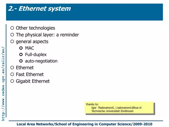
2.- Ethernet system. Other technologies The physical layer: a reminder general aspects MAC Full-duplex auto-negotiation Ethernet Fast Ethernet Gigabit Ethernet. thanks to: Igor Radovanovi ć , i.radovanovic@tue.nl Technische Universiteit Eindhoven . Other LAN technologies .

E N D
2.- Ethernet system Other technologies The physical layer: a reminder general aspects MAC Full-duplex auto-negotiation Ethernet Fast Ethernet Gigabit Ethernet thanks to: Igor Radovanović, i.radovanovic@tue.nl Technische Universiteit Eindhoven
Other LAN technologies Token Ring Token Bus FDDI
What is a Token Ring LAN? • A token ring network (IEEE 802.5) is a LAN technology based on a token-passing protocol for media access control. (No collisions) • Data frames are transmitted from node to node, in either a clockwise or counter-clockwise direction, over a point-to-point link. • A Token Ring LAN is implemented either: • Logical ring using a physical ring topology • Logical ring using a physical star topology (uses Token Ring Hubs that incorporate logical rings)
Terminology • Token Ring hubs are called Multistation Access Units (MAUs). • Nodes connected to a Token Ring network are called lobes; • The distance between MAUs is called the main ring length. • The distance between an MAU and its lobes is called lobe length. • IEEE 802.5 defined the specifications of Token Ring LANs, which is based in part on IBM’s set of token ring specifications. (IBM is the primary vendor of this technology)
Token Ring vs. Token Bus (1) • A Token Bus is a logical ring on a physical bus topology. It uses a token passing protocol (defined in IEEE 802.4). • The network is physically a bus topology and logically arranged as a ring with respect to passing the token from lobe to lobe. • Token Bus is based on broadcasting (similar to Ethernet/802.3), even thought token passing is point-to-point. • The Medium Access Control is similar to Token Ring (802.5). • At the physical layer, IEEE 802.4 uses coaxial cable or fiber-optic cable.
Token Ring vs. Token Bus (2) • Token Bus priority scheduling supports up to four priority modes (0 (lowest), 2, 4, and 6 (highest)). • Token Bus is not a popular LAN protocol, primarily used for control of industrial and factory automation processes.
Advantages and Disadvantages • Advantages: • its ability to run on many different media types • its efficient use of bandwidth • its stable behavior during high load times • its deterministic nature • its priority scheme, which enables nodes with high-priority data to reserve the network • Disadvantages: • need special recovery procedures when network fails • difficulty in configuring new hosts to an established LAN • in priority scheduling, the susceptibility of low priority nodes to increased delays in accessing the network.
FDDI: General aspects • Fiber Distributed Data Interface • MAC: Token Passing • Logical topology: Sequential • Physical topology: Dual counter-rotating rings. • Uses cable types: Fiber optic cable • Data rate/speed = 100 Mbps • Each cable length = 2 Km • Max # of cables = 100; Max # of repeaters = 100 • Max total Network length = 200 Km • Max # of nodes/segment = 10 • Max # of nodes/network = 1000
FDDI: Architecture basics • Primary ring---is the outer ring. • Secondary ring---is the inner ring. • Uses 2-types of Computers: DAS and SAS • SAS = Single attachment station • Connected to the outer/primary ring • DAS = Dual attachment station • Connected to both the primary/secondary rings. • If SAS/Primary ring fails, DAS takes over. • Each of these DASs/SASs must use FDDI-NIC.
2.- Ethernet The physical layer: a reminder general aspects MAC Full-duplex auto-negotiation Ethernet Fast Ethernet Gigabit Ethernet
Physical layer reminder: Terminology • Guided(wired) vs. Unguided(wireless) • examples of guided transmission media: • Twisted Pair • Coaxial cable • Optical fiber • point-to-point vs. multipoint • simplex, half-duplexandfull-duplex links
Physical layer reminder: Twisted Pair • pair • short connections (< 50m) • data rates < 19.2 kbps • Problems: • crosstalk • noise • twisted pair • often “bundled” into cables and usually installed in buildings during constructions • better than pair but still susceptible to interference and noise • Pros and Cons: • Cheap • Easy to work with • Limited data rate (100MHz) • Limited bandwidth (1MHz) • Limited distance • repeater every 2km or 3km
Physical layer reminder: Unshielded and Shielded Twisted Pair • Unshielded Twisted Pair (UTP) • Cheapest • Easiest to install • Suffers from external EM interference • Categories: • Cat 3 • up to 16MHz • Voice grade found in most offices • Twist length of 7.5 cm to 10 cm • Cat 4 • up to 20 MHz • Cat 5 • up to 100MHz • Commonly pre-installed in new office buildings • Twist length 0.6 cm to 0.85 cm • Shielded Twisted Pair (STP) • Metal braid or sheathing that reduces interference • More expensive • Harder to handle (thick, heavy)
Physical layer reminder: Coaxial Cable • Most versatile medium • two types: 50-ohm and 75-ohm • Long distance telephone transmission • Can carry 10,000 voice calls simultaneously • Being replaced by fiber optic • Short distance computer systems links • Local area networks • Analog • Amplifiers every few km • Closer if higher frequency • up to 500MHz • Digital • Repeater every 1km • Closer for higher data rates • up to 350 MHz (500 Mbps)
Physical layer reminder: Optical Fiber • Greater capacity • Data rates of hundreds of Gbps • Smaller size & weight • Lower attenuation • Electromagnetic isolation • Greater repeater spacing • 10s of km at least • problems with junctions • Applications: • Long-haul trunks • Metropolitan trunks • Rural exchange trunks • Subscriber loops • LANs
Physical layer reminder: Optical Fiber - Transmission Characteristics • Act as wave guide for 1014 to 1015 Hz • Portions of infrared and visible spectrum • Light Emitting Diode (LED) • Cheaper • Wider operating temp range • Last longer • Injection Laser Diode (ILD) • More efficient • Greater data rate • Wavelength Division Multiplexing: WDM and DWDM
Physical layer reminder: Encoding and modulation techniques g(t)[digital or analog] x(t) [digital] g(t) coder decoder m(t)[digital or analog] s(t)[analog] m(t) modulator demodulator fc
Physical layer reminder: Nonreturn to Zero-Level • NRZ-L:two different voltages for 0 and 1 bits • Voltage constant during bit interval • no transition,i.e., no return to zero voltage • Example:absence of voltage for zero, constant positive voltage for one • More often, negative voltage for one value and positive for the other • NRZ-I: Nonreturn to zero inverted on ones • Constant voltage pulse for duration of bit • Data encoded as presence or absence of signal transition at beginning of bit time • Transition (low to high or high to low) denotes a binary 1; no transition denotes binary 0
Physical layer reminder: Multilevel Binary mBnL codes: a sequence of m bits is represented by n pulses, each of L levels (n<m and L>2)
Ethernet: some historical notes... • 1972: Robert Metcalfe designs the first prototype at the Xerox PARC • 1980: the first standard appears, by DEC-Intel-Xerox • 1985: IEEE802.3 standard is released. The complete name is: “Carrier Sense Multiple Access with Collision Detection (CSMA/CD) Access Method and Physical Layer Specifications” • IEEE supplements • 802.3d-1987: FOIRL fiber link • 802.3i-1990: 10BASE-T twisted pair • 802.3z-1998: Gigabit Ethernet • 802.3ab-1999: 1000BASE-T Gigabit Ethernet over twisted pair • 802.3ae-2002: 10Gb/s Ethernet
The Ethernet “family tree” • 10Mbps • 10Base2 • 10Base5 • 10Base-T • FOIRL 10Base-F • 10Base-FB • 10Base-FP • 10Base-FL • 100 Mbps (100Base-T) • 100Base-X • 100Base-TX • 100Base-FX • 100Base-T4 • 1000 Mbps • 1000Base-X • 1000Base-SX • 1000Base-LX • 1000Base-CX • 1000Base-T 2 = thin coaxial; 5 = thick coaxial; T = twisted pair; F = fiber optics; S = short wavelength; L = long wavelength; C = short copper cable;
Devices • Hubs • Switches • Adaptors
Connection media • Different connection types are used by each physical layer implementation. • The registered jack (RJ-45) connector and jack are the most common. In some cases the type of connector on a NIC does not match the media that it needs to connect to. The AUI connector allows different media to connect when used with the appropriate transceiver.
Connection media • EIA/TIA specifies an RJ-45 connector for UTP cable. • The letters RJ stand for registered jack, and the number 45 refers to a specific wiring sequence. • The RJ-45 connector is the male component, crimped on the end of the cable.
Connection media • The jack is the female component in a network device, wall outlet, or patch panel.
Cable Standards • For electricity to run between the connector and the jack, the order of the wires must follow EIA/TIA-T568-A or T568-B standards. • Identify the correct EIA/TIA category of cable to use for a connecting device by determining what standard is being used by the jack on the network device.
Straight-through Cable • The 10BASE-T and 100BASE-TX Ethernet standards use one wire pair for transmission in each direction. This requires that the transmit pair of each device be connected to the receive pair of the device on the other end. • If the two RJ-45 connectors of a cable are held side by side in the same orientation, the colored wires will be seen in each. • If the order of the colored wires is the same at each end, then the cable is straight-through.
Straight-through Cable • Use straight-through cables for the following cabling: • Switch to Host (PC or server) • Hub to Host (PC or server) • Switch to router Rule of thumb: Connect devices of the same OSI Layer with CROSSOVER cable.Connect devices of different OSI Layers with STRAIGHT cables.
Crossover cables • One terminal device may be connected directly to another without the use of a switch or hub, but in that case the crossover must be done externally in the cable. Since 10BASE-T and 100BASE-TX use pairs 2 and 3, these two pairs must be swapped in the cable. This is a crossover cable. • When a terminal device is connected to a switch or hub, this crossover is done internally in the switch or hub. • Automatic crossover • Automatic MDI/MDI-X Configuration is specified as an optional feature in the 1000BASE-T standard meaning that straight-through cables will usually work between Gigabit capable interfaces. This feature eliminates the need for crossover cables, obsoletes the uplink/normal ports and manual selector switches found on many older hubs and switches, greatly reducing installation errors. • Note that although Automatic MDI/MDI-X is generally implemented, a crossover cable would still be required in the occasional situation that neither of the connected devices has the feature implemented and enabled. • Even for legacy 10/100 devices, many NICs, switches and hubs automatically apply an internal crossover when necessary. This feature may also be referred to by various vendor-specific terms including: Auto uplink and trade, Universal Cable Recognition and Auto Sensing.
Crossover Cable • With crossover, the RJ-45 connectors on both ends show that some of the wires on one side of the cable are crossed to a different pin on the other side of the cable. • Pins 1 and 2 on one connector connect respectively to pins 3 and 6 on the other.
Crossover Cable • Use crossover cables typically between like devices, for example: • Switch to switch • Hub to hub • Router to router • PC to PC Rule of thumb: Connect devices of the same OSI Layer with CROSSOVER cable.Connect devices of different OSI Layers with STRAIGHT cables.
Frame format in traditional Ethernet • MAC frame • Preamble • 7 bytes of alternating 0s and 1s – receiver sync • Not necessary in high-speed Ethernet systems (FastEth, GigE) • Start of Frame Delimiter • 10101011 – unique sequence -> last chance to synchronize • Source Address, Destination Address • 48 bit unique address • Length/Type • Value up to 1518: length; value larger than 1536 – type of PDU encaps • Data • Frame Check Sequence (CRC); Preamble and SFD excluded
Min & Max Ethernet frame length • Minimum length - used for CSMA/CD • Every end station senses the frame within the correct time limits • Historical requirement derived for bus topology with a coax cable and a network with a 2 byte field • Maximum length – to assure fair access • A station should not occupy the medium too long
Organizationally Unique Identifier as assigned by the IEEE 48-Bit Universal LAN MAC Addresses • Described in IEEE Std802-1990, pg. 25 • 48 bits burned into ROM on adaptor • Unicast address: destined for individual receiver • Broadcast address: all 1’s in address- for every node • Multicast address: leading 1 in address– subset of nodes Octet: 0 1 2 3 4 5 0011 0101 0111 1011 0001 0010 0000 0000 0000 0000 0000 0001 First bit transmitted on the LAN medium. (Also the I/G Address Bit: 0=Individual; 1=Group) Second bit, the Universally or Locally Administered, U/L Address Bit, indicates whether the address has been assigned by a local (=1) or universal administrator (=0). The hexadecimal representation is: AC:DE:48:00:00:80
Random Access MAC protocols CSMA/CD (Collision Detection) • CSMA/CD: carrier sensing, deferral as in CSMA • collisions detected within short time • colliding transmissions aborted, reducing channel wastage • persistent or non-persistent retransmission • collision detection: • easy in wired LANs: measure signal strengths, compare transmitted, received signals • difficult in wireless LANs: receiver shut off while transmitting • human analogy: the polite conversationalist
The CSMA with Collision Detection protocol while there are frames to be sent while (channel is busy)loop; /* the channel is available (idle) */ wait IFG << sending >> if a collision is detected then send jam signal abort the transmission wait a random amount of time whend
Binary Exponential Backoff -> ith collision <- if i 10 then choose a number n between 0 and (2i-1) wait n time-slots try sending again else if i 16 then choose a number n between 0 and (210-1) wait n time-slots try sending again else if i > 16 then error fi
CSMA/CD: a few details A B C time data interframe gap (IFG): 96 bits (9.6msec at 10Mbps) collision enforcement jam signal: 32 bits collision backOff time: multiples of the slot time: 512 bits
Collisions and minimum frame size A B A B t = t-e t=0 A B A B t = t t = 2t 1km coax cable, Tprop = d/Vprop~ 5msec; 2,5 km with 4 repeaters, measured 2t~ 51.2msec s = vt = 10Mbps·51.2msec = 512 bits=64bytes
Media System Timing • Depends on: • physical layer roud-trip propagation time • collision enforcement procedure • 512 bit time for 10 and 100 Mbps sytems • networks diameter in 10 Mbps systems: approx. 2800meters • networks diameter in 100 Mbps systems: approx. 205meters • In half-duplex Gigabit ethernet • networks diameter would be approx. 20 meters • The solution: carrier extension; it allows not to modify the frame structure i.e., 4096 bits
Frame bursting • Carrier extension is very inefficient for the short packets • for example for 64 byte packet we have 448 bytes of padding • low throughput • Solution: introduce Frame bursting • The maximum burst size is 65536 bit (8192 bytes) plus the final frame transmission
Definition of a collision domain • “defined as all the Ethernet segments between a pair of bridges or other layer 2 devices” • “a single CSMA/CD network in which there will be a collision if two computers attached to the system both transmit at the same time”
Segmentation • Segmentation is the process of splitting a single collision domain into two or more collision domains. Layer 2 bridges or switches can be used to segment a logical bus topology and create separate collision domains. However the entire bus topology still represents a single broadcast domain because, bridges and switches forward broadcast packets.
An example of a collision domain • A collision domain is also known as a bandwidth domain