Download
1 / 62
630 likes | 643 Views
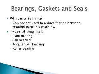
Different Types of Bearing Currents – The Fundamentals (plus). Mike Melfi. Different Types of Bearing Currents – The Fundamentals. Background Bearing Damage / Failure Mechanisms Causes Line-Fed Inverter-Fed Solutions Line-Fed Inverter-Fed Summary & Conclusions. Background.

E N D
Different Types of Bearing Currents – The Fundamentals (plus) Mike Melfi
Different Types of Bearing Currents – The Fundamentals • Background • Bearing Damage / Failure Mechanisms • Causes • Line-Fed • Inverter-Fed • Solutions • Line-Fed • Inverter-Fed • Summary & Conclusions
Background Q: Since bearing currents in rotating machinery have been documented for at least 75 years, why is this a contemporary issue?
Background Q: Since bearing currents in rotating machinery have been documented for at least 75 years, why is this a contemporary issue? A: Modern PWM inverters create both common mode voltages (CMV) and common mode currents (CMC) which provide new opportunities for current to flow through rotating bearings (along with couplings, gears, etc)
Background While the 75 year old sources of bearing currents are well understood and solutions exist, it is important to keep them in mind to avoid resurrecting them in trying to solve the challenges brought on by common mode voltages and currents.
Bearing Damage / Failure Mechanisms Individual arc damage spots Fluting in outer race, from prolonged operation after damage from current flow
Bearing Damage / Failure Mechanisms Fluting on inner race, from prolonged operation after damage from current flow Fluting in outer race
Bearing Damage / Failure Mechanisms • Interrupted current causes melting and “re-hardening” of the race material, creating untempered martensite, which is brittle and prone to fatigue
Bearing Damage / Failure Mechanisms Quenched and tempered ball bearing inner ring White Layer, untempered martensite
Bearing Damage / Failure Mechanisms • Interrupted current causes melting and “re-hardening” of the race material, creating untempered martensite, which is brittle and prone to fatigue • The normal bearing loads are then capable of breaking off small pieces of this brittle material • Subsequent running on this brittle surface and in the presence of the damage “trash” material creates the “fluting”
Bearing Damage / Failure Mechanisms • If the damaged material does not progress to a fluted pattern from subsequent running, two other patterns may be seen • A “frosted” surface may appear, or • A number of “pits” may be visible under high magnification • The verification of current flow as the root cause requires more than visual inspection
Sine Wave Bearing Currents • “If it were possible to design a perfectly balanced and symmetrical machine, both theory and practice indicate that no bearing current could exist” - C. T. Pearce, Bearing Currents - Their Origin and Prevention, The Electric Journal, August 1927.
Sine Wave Bearing Currents • Alternating flux “linking” the shaft … • Net flux encircling the shaftis typicallydue to asymmetric magnetic properties of stator or rotor core • Bearing current created by transformer action in “single turn” secondary (shaft, bearings, frame)
Flux path Shaft Boyd and Kaufman, 1959 Sine Wave Bearing Currents
Sine Wave Bearing Currents • Currents flow thru shaft, bearings, endshields, and frame • Axial voltage on shaft can be measured if a bearing is insulated (IEEE Std 112 - 1996) • Small shaft voltage (500 mV) can lead to bearing currents above 20 amps • Bearing damage is more likely to occur in larger machines
Common Mode Voltage / Current • Modern PWM drives create switching patterns where instantaneous average voltage to ground is not zero. • Voltage has a rapid change of magnitude with respect to time (dV/dt) • High dV/dt results in capacitively coupled currents from motor windings to ground through several paths I = C x dV/dt
Common Mode Voltage / Current PHASE VOLTS CMV
Common Mode Voltage / Current PHASE VOLTS CMV
Common Mode Voltage / Current PHASE VOLTS CMV
Common Mode Voltage / CurrentHigh Frequency Current Paths I = C x dV/dt
Common Mode Voltage / CurrentHigh Frequency End-End Circulation
Stator Winding Rotor + + CRF CSF Cb VCM - - Frame Bearing Csr VCM Bearing Voltage : Vb = Csr + Cb + Crf Common Mode Voltage / CurrentHigh Frequency Current Paths – Capacitive Charging of Rotor / Bearing CSR
Common Mode Voltage / CurrentTransient Frame Voltage Discharge
Common Mode Voltage / CurrentBearing Current Relative Magnitude
Bearing Current Solutions • Eliminate or reduce common mode voltage / current (Drive design issue) • Create best high frequency ground paths between drive,motor, and load • Electrostatic shielded induction motor • Insulated bearings • Shaft grounding brush
Bearing Current SolutionsInsulated Opposite Drive-End Bearing for Circulating Type Currents
Bearing Current Solutions - PrecautionsShaft Brush Without Opposite End Insulated Bearing (Larger Motor)(One Bearing at Increased Risk)
Bearing Current Solutions - PrecautionsInsulated Opposite Drive-End Bearing and Drive-End Shaft Brush(Bearings in Coupled Equipment Still at Peril)
Bearing Current SolutionsInsulated Opposite Drive-End Bearing, Drive-End Shaft Brush, and Coupled Equipment Bond Strap
Bearing Current SolutionsTwo Insulated Bearings, Drive-End Shaft Brush, and Coupled Equipment Bond Strap
Bearing Current Solutions – Faraday (Electrostatic) Shield • Add grounded conductive layer between stator and rotor • Eliminates stator to rotor coupling • Will not eliminate stator winding to frame coupling • Still need good high frequency ground current path from motor to drive ground
Bearing Current SolutionsFaraday Shield to Prevent Rotor Charging / Discharging (Bearings Still at Peril from Transient Frame Voltage Discharge when Shaft is Conductively Coupled to Grounded Equipment)
Bearing Current SolutionsFaraday Shield and Coupled Equipment Bond Strap
Bearing Current Solutions • Internal, end-end from magnetic asymmetry • Insulate opposite drive-end bearing • Insulate both bearings
Bearing Current Solutions • Shaft Extension Current (stray ground current) • Insulate coupling • Insulate bearings • Bond strap from motor to load • Better low impedance ground in cable from inverter to motor
Bearing Current Solutions • Discharge of voltage on rotor • Faraday (electrostatic) shield • Shaft brush
Measurements (Voltage) Common Mode Voltage Shaft Voltage 250 V/div 12.5 V/div
Measurements (Current) Shaft Extension Current(30 Amp Pulse)
Measurements • Other than internally-sourced circulating currents, all data is at high frequency • Data tends to be non-repetitive • Oscilloscope triggering technique strongly influences perceived results
Conclusions • Current flow in rotating bearings is not new • Common mode voltages and currents from modern inverters can cause current flow through bearings (plus couplings, gears, etc)
Conclusions • Corrective actions are dependent upon the particular type of current flow • Transient (high frequency) nature of the voltages and currents imposes different requirements than traditional 60 Hz waveforms
Conclusions • Since the sources of the currents as well as the paths are typically outside the machine whose bearings are taking the hit, a thorough understanding of the system is key • Grounding is important, but more in the sense of point to point (low impedance) “bonding” rather than “earthing”
Plus ... • Bonus material