Download
1 / 40
400 likes | 522 Views
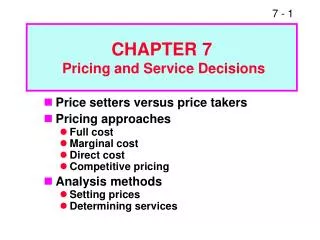
Chapter 7 Multicast and Realtime Service. Multicast. Unicast. Broadcast. Multicast. Multicasting is one-to-many or many-to-many communications. A simple implementation of multicasting can be built on top of the unicast (point to point) service …

E N D
Multicast Unicast Broadcast Multicast • Multicasting is one-to-many or many-to-many communications. • A simple implementation of multicasting can be built on top of the unicast (point to point) service … • Each multicast source send N-1 copies for total N subscribers in the multicast group that leads to an inefficient N2 problem • The desired case: a packet should be transmitted on one link exactly once • IP Multicasting uses less network resources. • IP supports multicasting via the help of IGMP and additional routing protocols.
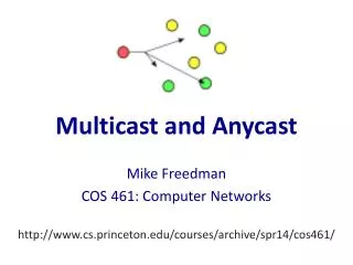
IP Unicast and Multicast • When A wants to send a packet to B, C and D • Unicast • A sends three copies of the packet, each to a different address. • Each copy may take a different path. • For a group of N nodes, N(N-1)/2 paths are needed. • Multicast • A sends one copy of the packet to a group address. • The packet will be forwarded in a multicast tree to B, C and D. • Less network resources are used.
IP Multicast Supported Services • DNS multicast query: provides a way to locate nearby name servers without knowing their IP addresses. The Recursion Desired bit should not be set in order to avoid excessive load on both network and DNS servers. • RIPv2 multicast RIP messages only to RIP routers (224.0.0.9) instead of to all routers in RIPv1. • SNMP implementation can use multicast to support group communication between managers and broker agents. • ICMP router solicitation and router advertisement: a host can multicast an ICMP router solicitation massage to all routers in this subnet (224.0.0.2) after bootstrapping to build its routing table. • IP Multimedia Streaming for video teleconferencing, Internet audio, and video streaming.
IP Multicasting Key Components • Multicast addressing • Define a common group address for all nodes in a group. • Map a multicast group address to a MAC address. • Multicast group management • The multicast group is dynamic, meaning that users may join and leave the group during the multicast session. • A multicast router needs to keep track of the memberships of the multicast groups. • A participant may want to know who else is in the group. • Multicast routing • Find and maintain a multicast tree from a participating node to all other nodes in the group. • The tree should be updated when • The network topology changes, or • The group membership changes.
Semantics of IP Multicast • A multicast group consists of a number of participating hosts. • Multicast groups are identified by a class D address. • Hosts (more precisely: interfaces) can join and leave a multicast group dynamically. • Every IP datagram sent to a multicast group is transmitted to all members of the group.
1 1 1 0 multicast group id Class D 28 bits Class From To D 224 .0.0.0 239 .255.255.255 IP Multicast Addressing • Desired properties of multicast group addressing • Decouple group from group members • Dynamic group members for a well-known group • All Class D addresses are designated as multicast IP addresses
Reserved Multicast Addresses • Examples of reserved IP multicast addresses:
Ethernet Multicast Address • A 48-bit long Ethernet address consists of • A 23-bit vendor component • A 24-bit group identifier: assigned by vendor • A multicast bit: set if the address is an Ethernet multicast address. • An example • The vendor component of Cisco is 0x00-00-0C. • A multicast Ethernet address assigned to Cisco starts with 0x01-00-0C.
Multicast Address Mapping • Ethernet addresses corresponding to IP multicasting are in the range of 01:00:5e:00:00:00 to 01:00:5e:7f:ff:ff. • At the sender, a multicast destination IP address is directly mapped to an Ethernet multicast address. • No ARP request and reply are needed. • Only the last 23 bits of the IP address is mapped into the multicast MAC address.
Multicast Address Mapping • Mapping procedure is not unique • Only 23 bits of an IP multicast address are mapped into the Ethernet multicast address. • 25=32 Class D IP addresses will map to the same multicast Ethernet address (since there are 5 bits ignored) • Example: 224.128.64.32 (hex: e0.80.40.20) and 224.0.64.32 (hex: e0:00:40:20) both map to 01:00:5e:00:40:20. • Ethernet device driver or IP module may need to perform packet filtering since the interface card may receive multicast frames in which the host is really not interested.
Multicast Address Mapping • At the receiver • The upper layer protocol should be able to ask the IP module to join or leave a multicast group. • The IP module maintains a list of group memberships, which is updated when an upper layer process joins or leaves a group. • The network interface should be able to join or leave a multicast group. • When a network interface joins a new group, its reception filters are modified to enable reception of multicast Ethernet frames belonging to the group. • A router interface should then be able to receive all the multicast IP datagrams.
IGMP • Internet Group Management Protocol (IGMP) is used by multicast routers to keep track of membership in a multicast group. • IGMP is originally defined in RFC 1112. IGMPv2 and IGMPv3 are defined in RFC 2236 and RFC 3376 respectively. • Support for: • Joining a multicast group • Query membership • Send membership reports
14 bytes 20 bytes 8 bytes Ethernet Header IP header IGMP Message Version Type Unused Checksum IGMPv1 32-bit Multicast Group Address Type Max Resp. Time Checksum IGMPv2 32-bit Multicast Group Address IGMP Packet Format and Revisions • IGMP messages are carried in IP datagrams with protocol number 2. • IGMPv1 and IGMPv2 messages are only 8 bytes long. • IGMPv1 • Type: 1 for a query from a router, and 2 for a report from a host. • IGMPv2 • Type: • 0x11 for membership query, • 0x16 for version 2 membership report, • 0x17 for leaving the group, • 0x12 for version 1 membership report to maintain backward-compatibility with IGMPv1. • Max Resp Time: applicable only to query messages, specifying the maximum allowed time before sending report message in units of 1/10 sec.
IGMPv1 Multicast Group Management • Multicast router periodically send host membership queries to discover which multicast groups have members on their attached local networks. • By default, the queries are sent at 60 second intervals. • Queries are sent to the class D address 224.0.0.1 (all host in the subnet) with a TTL of 1. • Multicast router maintains a multicast group membership table. • The table records which groups have members in the local networks attached to each interface of the router. • The router uses the table to decide which ports to forward a multicast datagram to.
IGMPv1 Multicast Group Management • A host responds to a IGMP query with an IGMP report for each multicast group in which it is a member. • The destination IP address is identical to the multicast group it is reporting on. • In order to avoid a flood of reports, a host delays an IGMP report for a random amount of time. If it overhears a report reporting on the same group address, it cancels the report. • When a host leaves a multicast group • It does nothing. Its membership record at the router will expire and be removed. • In later version of IGMP, it may report to all routers (with Type value of 0x17).
IP Multicast Routing • A critical issue in support IP multicast is how to find the multicast trees at a moderate cost • The participants in a group could be in different geographical locations. • A user can join and leave the multicast session at will. • The size of a group could be 1 or larger. • IP multicast routing protocols: • Distance Vector Multicast Routing Protocol (DVMRP) • Multicast Extension to OSPF (MOSPF) • Core Based Tree (CBT) • Protocol Independent Multicast (PIM)
DVMRP • DVMRP is a distance vector based multicast routing protocol. Has the count-to-infinity problem as RIP. • A DVMRP router exchanges multicast routing information with its neighbors and builds the multicast routing table. • Flood-and-prune approach is used in routing. • DVMRP assigns various values to the TTL field of multicast datagrams to control the scope of the broadcast. • Each link can be assigned with a TTL threshold in addition to the routing cost. • A router will not forward a multicast/broadcast datagram if its TTL is less than the threshold.
Flood-and-Prune in DVMRP • A source broadcasts the first multicast IP datagram. • A router R forwards a multicast packet from source S if, and only if, • The packet comes from the shortest route from R back to S. (Reverse Path Forwarding) • R forwards the packet only to the child links for S. • A Child link of R for S: the link that has R as parent on the shortest path tree where S is the root. • The child links are found by the multicast routing updates. • Prune • A DVMRP router that has no record of the membership in the multicast group sends a prune message to the upstream router. • The upstream router then will stop forwarding the remainder of the packets • Grafting • A DVMRP router that realizes new membership in the multicast group through IGMP sends a grafting message to the upstream router. • The upstream router then will resume the packets forwarding.
MOSPF • MOSPF is a Link State Algorithm (LSA) based intra-domain multicast routing protocol • each router maintains the entire topology of the network • each router run Dijkstra's shortest path algorithm to get shortest path to each destination • To incorporate multicast – a new group membership LSA is used to include group membership in link information • MOSPF, like DVMRP, uses multiple multicast trees with each source as the root, i.e. Per Source Tree • MOSPF, like DVMRP, performs tree calculation on-demand triggered by the 1st arriving multicast packet to a group
CBT • Per Source Tree is very costly • Core Based Tree (CBT) is also called as Shared Tree for all the sources in the multicast group • Core Based Tree forms an hierarchical structure • A Core router is chosen first • All other tree routers request to Join the core to build the routing table for each multicast group
CBT • CBT does not broadcast the first datagram. • Traffic load is greatly reduced. • Suitable for multicasting in large-scale and dense networks. • The routing table size is greatly reduced • A router only needs to store information for each multicast group • The number of CBT router entries is the same as the number of active groups. • Different from DVMRP and MOSPF • In DVMRP and MOSPF, a router stores information for each source in each multicast group • In DVMRP router, entries of Σi ∈(active groups) (No. of sources in group i ). • CBT has the traffic concentration problem • All source traffic may concentrate on a single link • May lead to congestion and a larger delay than multiple-tree schemes.
Two types of multicast routing protocols • Source-tree based protocols • Facilitate a more even distribution of the multicast traffic • Multicast datagrams from a source are distributed in the shortest path tree, resulting in a better delay performance • Each multicast router has to maintain state for all sources in all the multicast groups. Too costly for a large number of multicast sessions. • Shared-tree based protocols • Use a shared tree for all the sources in a group. Greatly reduce the number of states in the routers • Has the traffic concentration problem • The shared tree may not be optimal for all the sources, resulting in larger delay and jitter. • The performance depends on how the Rendezvous Point is chosen.
PIM • It is difficult to find a single protocol which is suitable for all scenarios, with various • Number of participants and their locations • Number of sources • Traffic sent by each source • Protocol Independent Multicast protocol (PIM) has two modes: • Dense mode • Source-based trees are used, works like DVMRP • For a high-rate source, its local router may initiate a switch to the source-based tree mode and use a source-based shortest path tree • Sparse mode • A shared tree is used, works like CBT
MBone • MBone stands for the multicast backbone. • Created in 1992, initially used to send live IETF meetings. • has evolved to become a semi-permanent IP multicast testbed. • MBone is an overlay network with a double-layer structure. • Lower layer • consists of a large number of multicast islands (local networks that directly support IP multicast). • Multicast IP datagram are sent and forwarded within the islands. • Upper layer • consists of a mesh of point-to-point links, or tunnels, connecting the islands. • A multicast IP datagram is encapsulated in a unicast IP datagram when sent through a tunnel.
Configuring a Multicast Router • Please read section 7.2.5 for • Configuring IGMP • Configuring multicast routing • Cisco IOS multicast diagnostic tools
Realtime Multimedia Streaming • Realtime multimedia applications • Video teleconferencing • Internet Telephony (VoIP) • Internet audio, video streaming The Architecture of video streaming
Realtime Streaming • QoS concerns – TCP/IP protocol suite is not designed to accommodate realtime traffic • Lack of support to synchronous, real-time demands • Traffic loss and variable delays (due to bandwidth limit, non-cooperative network behavior from other data traffic) • Long call setup time • Connection-less nature • Reliability
Jitter Control • Jitter: the variation in the inter-arrival times of received packets • Jitter Control • Larger playout delay, each frame is due to play at a later time, makes the real time streaming application more tolerable to jitter • Interactive realtime applications, like VoIP, require tight jitter control due to the strict requirement on end-to-end round trip delay An example: the playout buffer is used to absorb jitter
More Streaming Performance Requirements • End-to-end transport control • Sequencing – need it in upper layer since UDP does not support sequence numbering • Timestamping – for playout, jitter and delay calculation • Payload type identification – for media interpretation • Error control – need it on upper layer since UDP/IP does not support Forward Error Control (FEC), ARQ, … • Error concealment – method to cover up errors from lost packets by using the redundancy in most adjacent-frame image information • Quality of Service (QoS) feedback – from the receiver to the sender for operation adjustment • Rate control – from the sender to reduce sending rate adaptively to network congestion • Network support • Bandwidth reservation • Call admission and scheduling policy • QoS specific routing • Traffic shaping and policing
Protocol Stack for Multimedia Services • Application protocols supporting multimedia services: • Realtime Transport Protocol (RTP) • Realtime Transport Control Protocol(RTCP) • Real Time Streaming Protocol (RTSP) • Session Initiation Protocol (SIP) • Basic components: SIP user agent and SIP network server • Widely used in IP telephony. • Transport layer protocols • UDP is usually used for multimedia services • TCP is not used for a number of reasons • The delay and jitter caused by TCP retransmission may be intolerable • TCP does not support multicast • TCP slow-start may not be suitable for realtime transport.
RTP Introduction • Provides end-to-end transport functions for real-time applications • Support different payload types • Delay-oriented protocol rather than loss-oriented (such as TCP) • Usually carried over UDP with port number varying with application (default = 5004) • Does NOT provide timely delivery or other QoS guarantees • Relies on other protocols like RTCP and lower layers • Does NOT assume the underlying network is reliable and delivers packets in sequence • Uses sequence number • New style – Application level framing and integrated layer processing • Deliberately not complete • Often integrated into the application rather than a separate module • Complete specification of RTP for a particular application needs other documents • Profile specification documents defines sets of payload type codes, and their mapping to payload formats • Payload format specification document define how to carry a specific encoding
RTP • RTP provides essential support for multimedia streaming and distributed computing • RTP encapsulates realtime data • RTCP provides QoS monitoring and session control • RTP/RTCP are application layer protocols • Usually integrated into applications • Independent of the underlying transport and network layer protocols • Does not provide timely delivery or other QoS guarantees • Rely on the lower-layer protocols for reliable service
RTP Packet Format • Version (V, 2bits): =2 • Padding (P, 1bit): If set to 1, last byte of payload is padding size that aligns the payload to the 32-bit word boundary • Extension (X, 1bit): If set, variable size header extension exists • CSRC Count (CC, 4bits): indicates the number of contributing source (CSRC) identifiers that follow the common header • Marker (M, 1bit): used to mark a significant event in the payload (e.g., the boundary of a video frame) • Payload Type (PT, 7bits): identifies the format of the RTP payload and determines its interpretation by the application
RTP Packet Format • Sequence Number (16bits): the sequence number of the RTP packet. Can be used for loss detection and resequencing. • Timestamp (32bits): identifies the sampling instant of the first octet of the RTP payload, used for synchronization and jitter calculation. • Synchronization Source (SSRC) Identifier (32bits): identifies the synchronization source (the source of a RTP packet stream). • Contributing Source (CSRC) Identifier List: 0 to 15 items, each with 32bits. The list of identifiers of the sources whose data is carried in the payload.
RTCP Packet Types • Sender Report (SR): statistics from active sender • May also includes RR blocks • Receiver Report (RR): statistics from participants that are not active senders • RTCP RR packet sent if a node is only a receiver • Source description item (SDES) • BYE: indicates end of participation • APP: application specific functions
RTCP Sender Report Format Header Sender Info Report Block 1 Report Block 2
RTCP Sender Report Fields • RTCP Header: • Version (V) and Padding (P): As described for RTP data packet above • Packet Type (PT, 8 bits): The packet type constant 200 designates an RTCP SR packet. RTCP RR is 201. • Length (16 bits): The length of this RTCP packet in 32-bit words minus one, including the header and any padding. • Sender information block: • NTP timestamp: wallclock time (absolute time as per Network Time Protocol) when packet is sent • RTP timestamp: time when packet is sent according to the clock used to send RTP data packet timestamps; used for intra&inter media synchronization • Sender’s packet count: total number of packets sent since the start of session • Octet count: total number of bytes sent since the start of session
RTCP Sender Report Fields • Multiple receiver report blocks, one for each source from this host receives packets • SSRC_n: identifies source whose data this report block is about • Fraction lost: fraction of packets lost since last report was sent • Cumulative number of lost packets since the beginning of reception • Highest sequence number received • Inter-arrival jitter • Last SR (LSR): The NTP timestamp of the last sender report received from the source • Delay since Last SR (DLSR): Delay between receiving the last SR from this source and sending this RR
Multimedia Streaming Example • RTCP • QoS feedback reports containing number of packets lost at receiver, interarrival jitter that allows senders to adjust data rate • Binding across multiple medias sent by a user (SDES) • Rate control of RTCP packets by noting how many participants are on session • Minimal session control • Real Time Streaming Protocol (RTSP) • Internet VCR remote control, initiating and directing realtime streaming • Transported using UDP or TCP • Works with RTP/RTCP for controlled streaming